In-Situ and Numerical Investigation of Groundwater Inrush Hazard from Grouted Karst Collapse Pillar in Longwall Mining


1
School of Resources & Safety Engineering, Central South University, Changsha 410083, China
2
Research Center of Coal Resources Safe Mining and Clean Utilization, Liaoning Technical University, Fuxin 123000, China
*
Authors to whom correspondence should be addressed.
Water 2018, 10(9), 1187; https://doi.org/10.3390/w10091187
Submission received: 30 July 2018
/
Revised: 25 August 2018
/
Accepted: 31 August 2018
/
Published: 4 September 2018
(This article belongs to the Special Issue Hydraulic Behavior of Karst Aquifers)
Abstract
:Groundwater inrush is a typical hydrologic natural hazard in mining engineering. Since 2000 to 2012, there have been 1110 types of mine groundwater inrush hazards with 4444 miners died or missing. As a general geological structure in the northern China coalfields, the karst collapse pillar (KCP) contains a significant amount of granular rocks, which can be easily migrated under high hydraulic pressure. Therefore, the KCP zone acts as an important groundwater inrush pathway in underground mining. Grouting the KCP zone can mitigate the risk of groundwater inrush hazard. However, the fracture or instability of the coal pillar near KCP can cause the instability of surrounding rock and even groundwater inrush hazard. To evaluate the risk of groundwater inrush from the aquifer that is caused by coal pillars instability within grouted KCP in a gob, an in-situ investigation on the deformation of the surrounding strata was conducted. Besides, a mechanical model for the continuous effect on the coal pillar with the floor-pillar-roof system was established; then, a numerical model was built to evaluate the continuous instability and groundwater inrush risk. The collective energy and stiffness in the floor-pillar-roof system are the two criterions for judging the stability of the system. As a basic factor to keep the stability of floor-pillar-roof system, the collective energy in coal pillar is larger than that in floor-roof system. Moreover, if the stiffness of floor-roof or coal pillar meets a negative value, the system will lose stability; thus, the groundwater inrush pathway will be produced. However, if there is a negative value occurring in floor-pillar-roof system meets, it indicates that the system structure is situated in a damage state; a narrower coal pillar will enlarge the risk of continuous instability in the system, leading to a groundwater inrush pathway easily. Continuous coal pillars show a lower probability of instability. Conversely, the fractured coal pillars have a greater probability of failure. The plastic zone and deformation of the roadway roof in the fractured coal pillar are larger than that of continuous coal pillar, indicating that the continuous coal pillars mitigate the risk of groundwater inrush hazard effectively.
1. Introduction
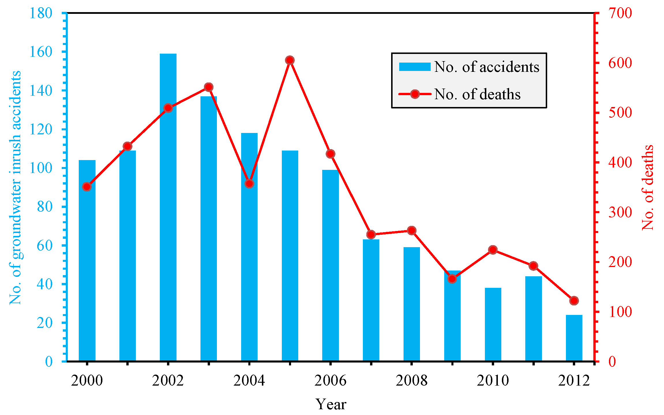
With the increase of mining depth, difficulty, and production for coal resource in China, the mining-induced hazard occurs frequently, such as the water inrush accidents. It is pointed out that more than 90% of the groundwater inrush accidents are caused by the groundwater flow from karst aquifers [1]. According to the statistics in Figure 1, hundreds of miners are killed by mine water inrush accidents each year. With the progress of water inrush prevention, the number of groundwater damage accidents in coal mines is declining. However, since 2000 to 2012, 1110 types of mine groundwater inrush accidents have been reported, with 4444 miners died or missed [2]. Furthermore, water inrush disaster affects the safe mining, causes major labor and economic loss, but also makes a serious pollution to the geological environment by mine drainage [1]. After unremitting efforts for establishing safe mining environments [3], Chinese scientists have made great achievements in predicting and preventing fatal mine water inrush accidents.
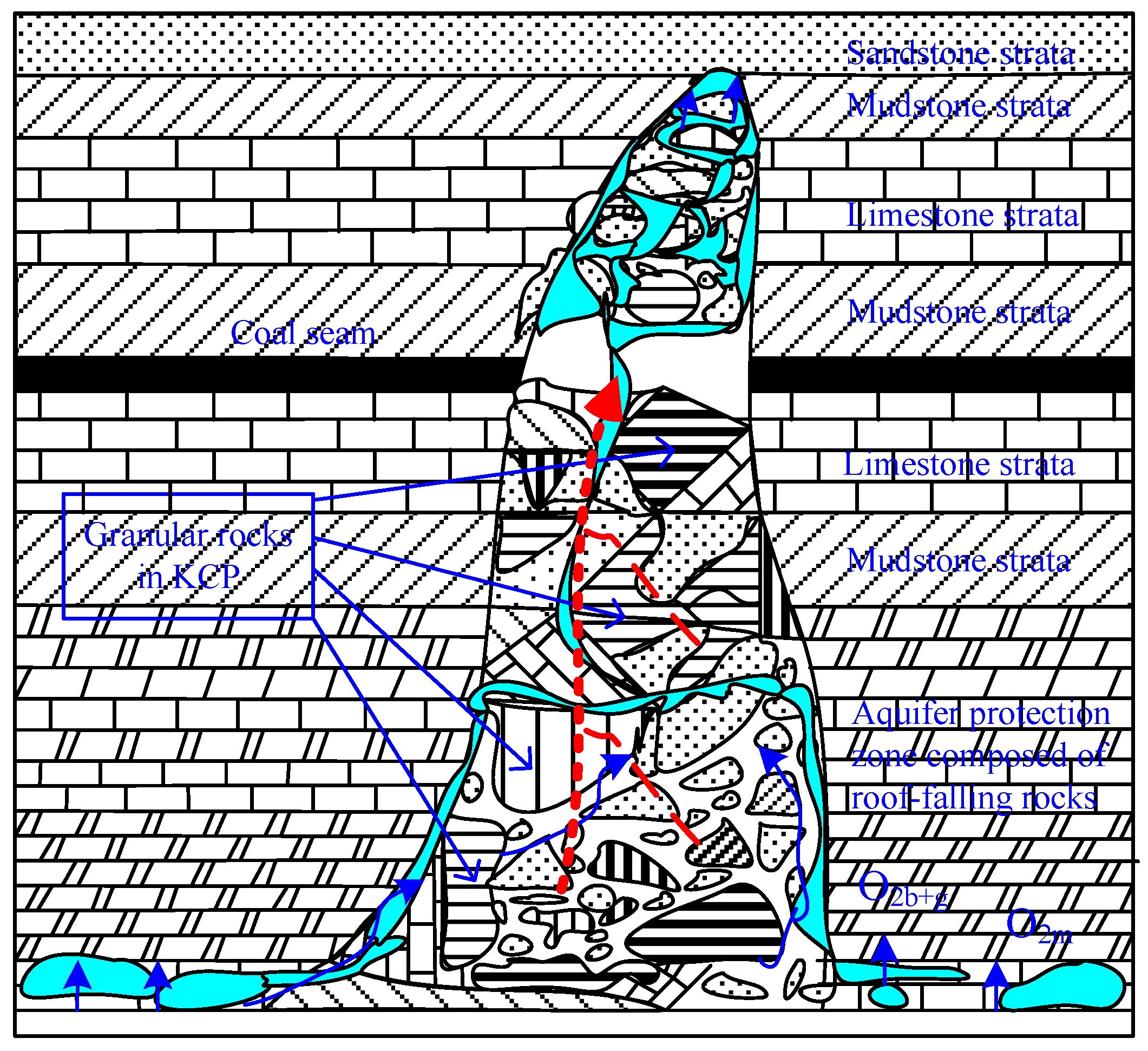
Due to strong corrosion of the groundwater flow, the underlying soluble rock layer is prone to forming a large number of cavities therein. Subsequently, the overlying strata loses its stability, rock fragments fall into the cavitation space, and finally karst collapse pillar (KCP) is formed. As a typical hazard-causing geologic structure, KCP is widespread in the coalfields of northern China [4]. As shown in Figure 2, the KCP zone contains a significant amount of rock fragments (granular rocks), which can be easily migrated under high hydraulic pressure. Therefore, KCP zone acts as an important groundwater inrush pathway in underground mining [5,6].
Recently, scholars have paid more and more attention to the study of the groundwater inrush mechanism. To analyze and predict groundwater inrushes from aquifers, a lot of analytical models and empirical standards have been proposed, including the plate model [7,8], hypothesis of three zones in roof strata [9], groundwater inrush index [10], key strata model [11], GIS-based forecasting model [12,13], fluid-solid coupling model [14,15], and synthetic approaches (see the comprehensive reviews by [16]). Some experimental techniques [5,17,18,19] and the in-situ testing [20] have been conducted. These theoretical researches promote the risk assessment of groundwater inrush hazards in rock engineering [3,21,22]. However, it is worth noting that coal pillar instability might also result in water inrushes from aquifer through overlying coal seam. Later, the height of water-flowing fissure zone of overlying strata is enlarged [11]. If the groundwater inrush pathway is connected with the overlying aquifer [23], the groundwater inrush hazard will occur easily.
Recently, several theoretical researches and experiments on KCP and the relevant granular rocks have been conducted. A mechanical model for describing the groundwater seepage in coal seam floor within the KCP was established by Bai et al. [14]. Coal mining brings damage to KCP and its surrounding rocks, resulting in a fracture formation. A hydrologic-mechanical coupling model was obtained to simulate the hydrologic law by Ma et al. [6]. Besides, the mining effect on water inrush hazard, which is caused by hydrologic instability in KCP, was analyzed in detail. To ensure the safety of underground mining, grouting reinforcement of the KCP and floor bedrock is usually used for (1) increasing the KCP tensile strength and floor bedrock; and, (2) mitigating the groundwater inrush risk in coal mining [3]. However, due to the weakness of surrounding rocks within KCP, the fracturing of the coal pillar near KCP can cause the instability of surrounding rock and the increase of the seepage ability, finally resulting in groundwater inrush hazard.
To investigate the risk of coal pillar instability on groundwater inrush from the grouted KCP, an in-situ investigation on the deformation of overlying strata was conducted. Besides, a mechanical model for the continuous effect on the coal pillar with the floor-pillar-roof system was established; then, a numerical model in fast Lagrangian analysis of continua in three dimensions (FLAC3D), was also used to simulate the continuous instability and groundwater inrush risk from the grouted KCP within a coal pillar in gob.
2. General Deformation and Groundwater Inrush Risk of Overlying Strata
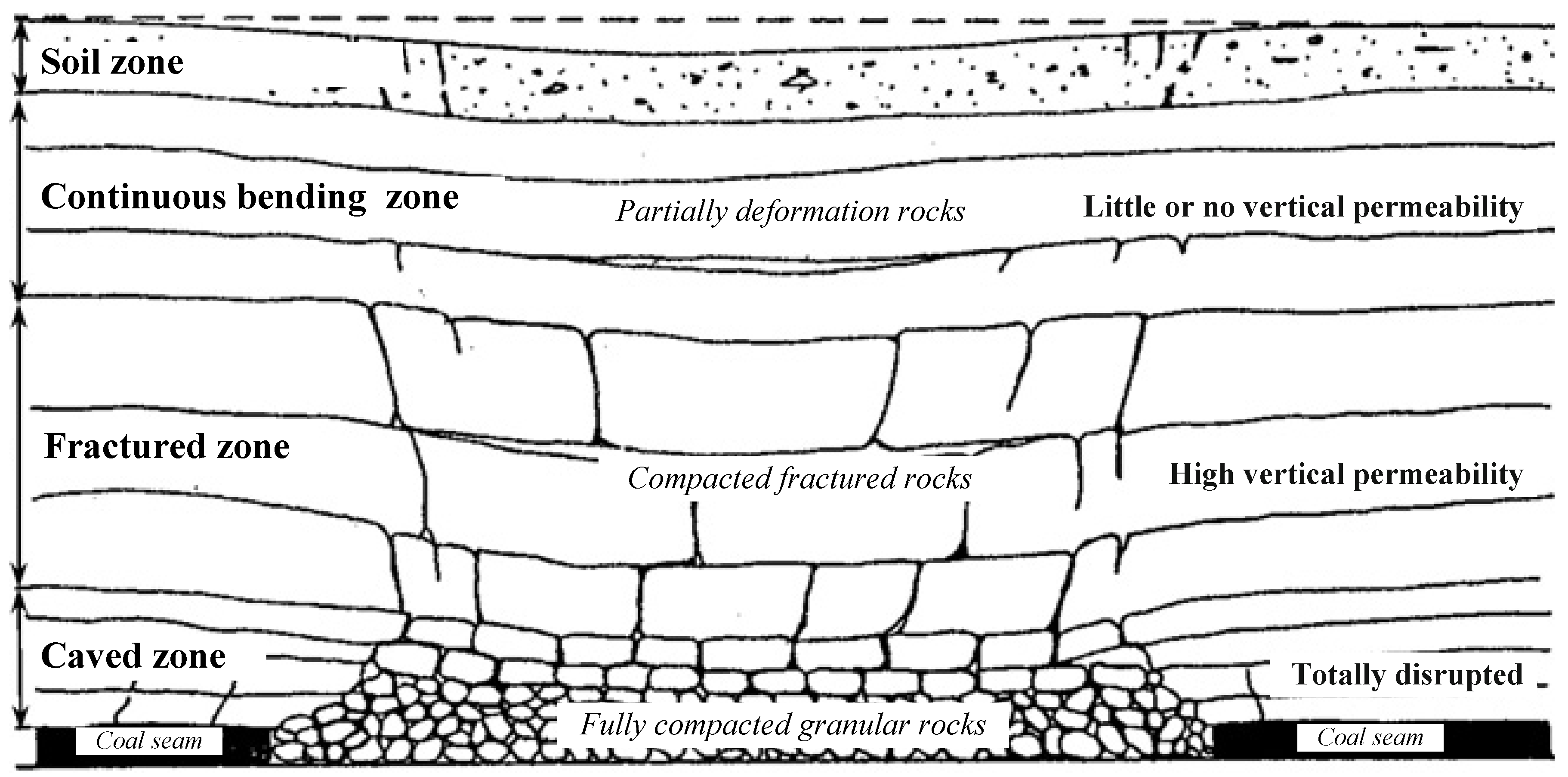
After adequate extraction of the coal seam in the longwall mining or room-pillar section, the overlying strata are deformed to varying degrees. According to the deformation characteristics in Figure 3, the fractured overlying strata are divided into four zones [24]. Therefore, the fracture severity can be described clearly in decreasing order. Groundwater effects from the immediate roof toward the surface can be analyzed systematically [11].
2.1. Soil Zones
As the surface layer, this zone is composed of weathered rock and soil. The thickness of soil zone determines its location. Physical properties of soil determine the openness or closure of fissures, which are opened with the approaching coal face and closed again after the departure of the mining excavation face. However, some fissures may continue to be opened after the departure of coal face, particularly those forward lines of mining panels. Fracture walls are prone to collapse and infill these cracks.
2.2. Continuous Deformation Zones
Due to the strata continuity and its original bedding features, the strata beyond the fractured zone are inclined downwards without significant breakage. In certain conditions, its impermeability was lost temporarily and soon recovered. Some opening fractures occasionally develop in the tension zone without breaking the continuity of strata generally. The above two zones are usually treated as aquiclude (water-resisting layer) in the previous literature [15,21]. Owing to the low permeability, these two zones are significant for the groundwater inrush prevention in mining and groundwater protection.
2.3. Fractured Zones
Discontinuity and strata breakage are fundamental features in the fractured zone, but the rock remains stratified bedding. As the strata breakage upward decreases, there is a reduction in the permeability. The total height of the fracture and caved zones is around 9–11 times than the excavation height in soft or weak strata; 12–15 times in medium hard strata; and, 20–30 times in hard or strong rock, respectively. In other words, there is a lower height of the fractured zone in weak and soft strata than that in strong and hard strata [23]. The permeability of fractured rocks is greater than that of bending rocks, namely the risk of groundwater inrush accidents is increased in fractured rocks.
2.4. Caved Zones
After mining the coal, the immediate roof strata are caving to the irregular and void zone. Stratified bedding of the strata is discontinuous and loose in this zone. The height of caved zone is commonly 2–8 times than the excavation height, relying on characters of the overlying strata and the immediate roof. Groundwater accidents usually occur in these areas due to the high permeability of the crushed rocks in the caved zone [25].
3. In-Situ investigation on the Deformation of Overlying Strata
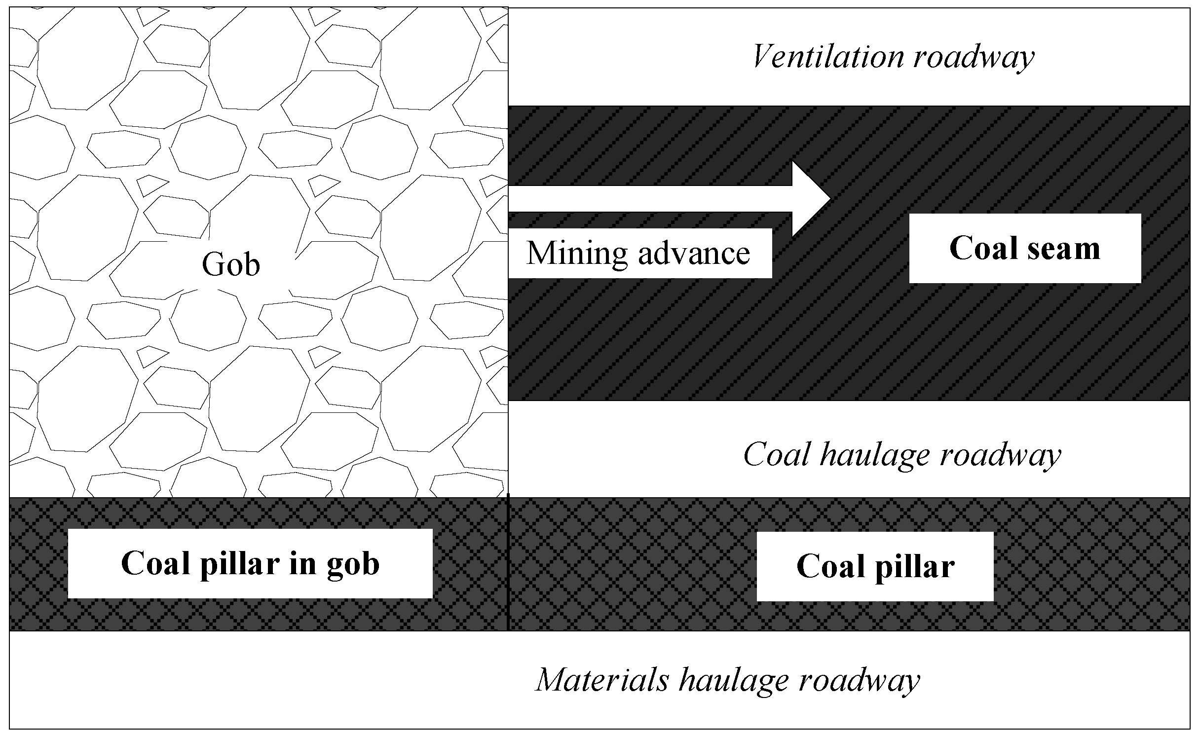
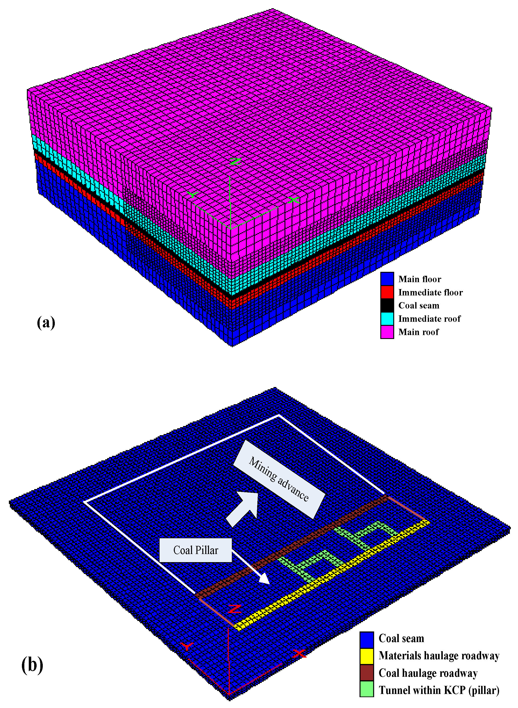
Xiaojiawa Coal Mine is located in Lvliang, Shanxi Province, China, whose surface topography beyond the coal face 211301 is relatively undulating with an altitude of 1208–1225 m. The mining panel along the crash is 2561.2 m in length and 240 m in dip width. As the Jurassic system, the main strata consist of 18 layers of distinct strata in the region. The bedrock has a thickness of 250–310 m. Generally, the alluvium ranges from 58.7–74.6 m in thickness. Coal mining is conducted by the integrated mechanized longwall mining, the position of the coal pillars in a gob is shown in Figure 4. It can be seen that coal pillars are left to control the deformation of overlying strata.
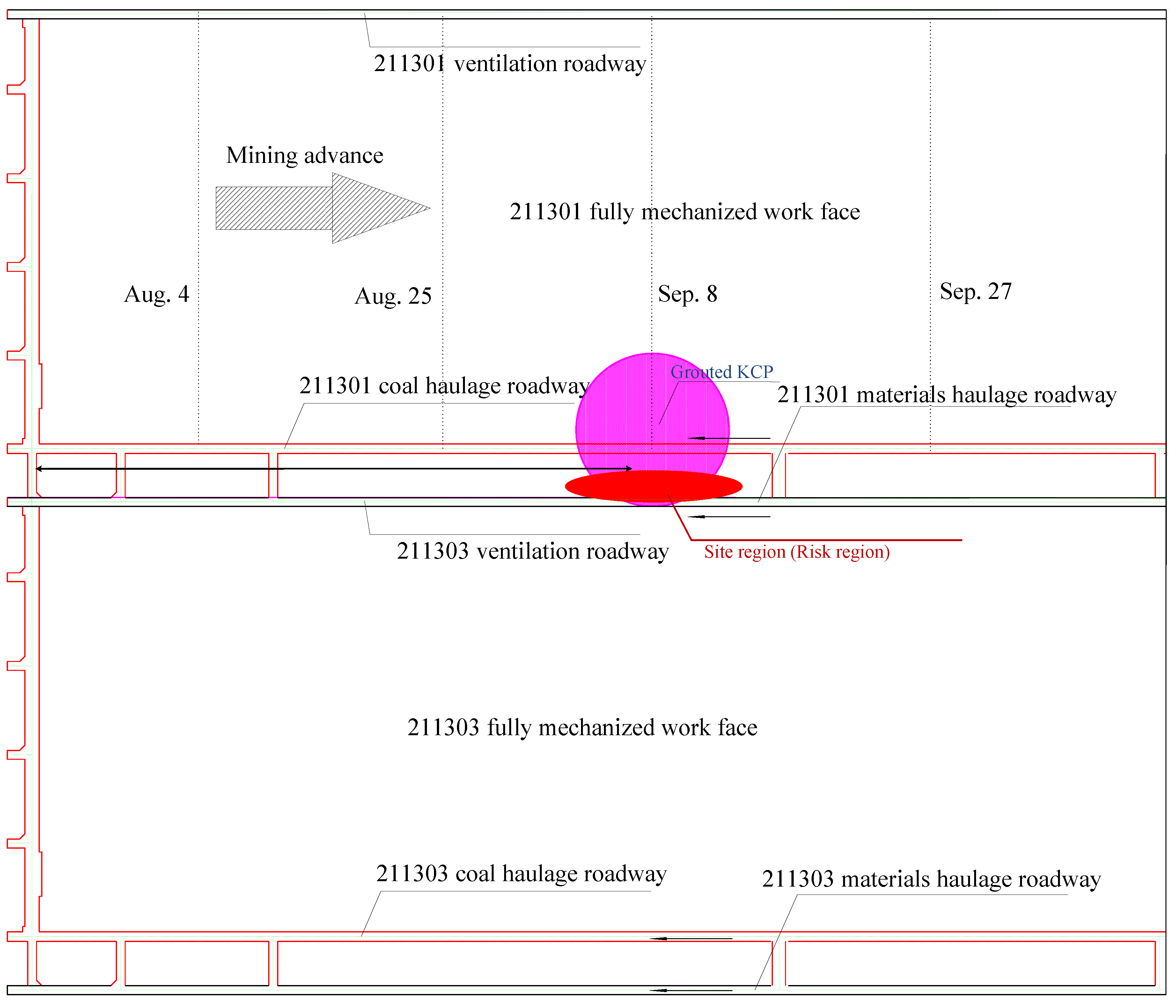
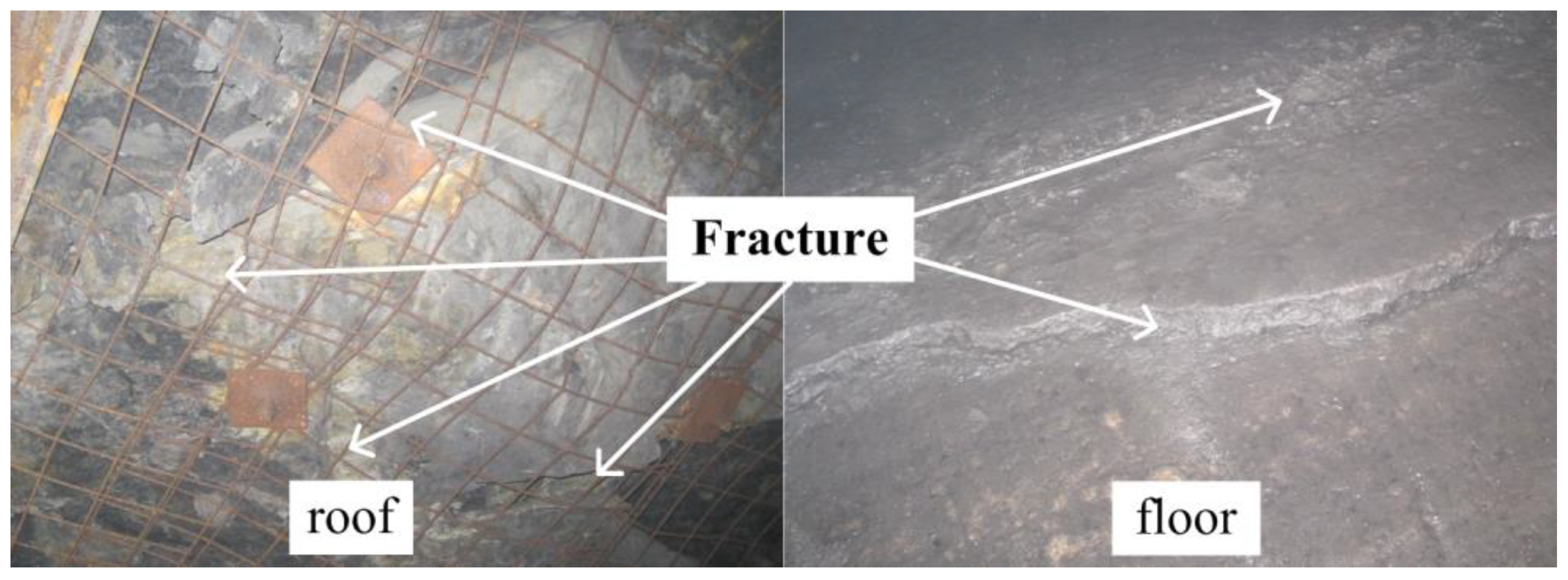
When considering the site conditions of working face 211301, KCP grouting reinforcement and floor bedrock are taken to mitigate the water inrush risk in the mining process. The site region (risk region) is located above material transportation roadways, as shown in Figure 5. As there are two connection tunnels within grouted KCP in the coal pillar, partial pillar is empty, leading to the pillar instability. The mining time for the area is 8 September 2013. The fracture (failure) of the roadway roof and floor is shown in Figure 6. The in-situ testing subsidence in the area is shown in Table 1.
As shown in Table 1, the decrease of the roadway height is greater than roadway width. Apparently, the instability of coal pillar has a crucial effect on the deformation of the overburden strata, especially the at the distances of 10, −4, −16, and −35 m from the KCP, the roadway subsidence is 0.36, 0.46, 0.27, and 0.35 m, and whose roadway deformation are 14.08%, 19.49%, 11.48%, and 15.2%, respectively. This indicates that the tunneling situation within grouted KCP has a significant impact on the coal pillar instability and the corresponding subsidence of the overlying strata.
4. Modeling of the Coal Pillars Instability on the Strata Deformation
A mechanical model for the continuous effect on the coal pillar with the “floor-pillar-roof” system is described in this section.
4.1. Instability Conditions of a Floor-Pillar-Roof System
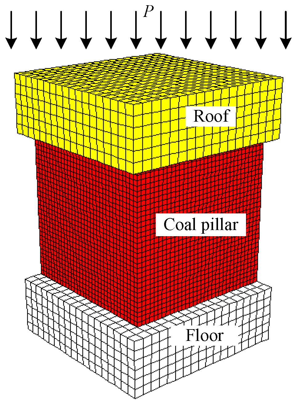
As shown in Figure 7, P in the stress mesh model indicates the mining effect on the whole coal system. The relationship between mining-induced stiffness and system instability is concluded by the energy evolution [26,27,28]. Assuming that there is no deformation in the floor, the coal pillar and roof act together, and the force in the coal pillar is a function of displacement and time, and then the force from the overlying strata on the top of the roof and the pillar are expressed as:
where and are the load on the roof and a coal pillar, respectively; , and are the mass, stiffness, and displacement of the roof, respectively; and are the stiffness and displacement of the coal pillar, respectively.
If the system is in a balanced state, these two forces should be equal, namely . Therefore, the equation is expressed as:
To keep the stability in the system, the accumulated energy in the roof and floor should be less than that in the coal pillar , i.e., .
4.2. Static and Dynamic Destruction of the System
There are two instability methods of the “floor-pillar-roof” system, namely the static and dynamic states.
4.2.1. Static Destruction
When static destruction occurs, the system is relatively stable and the kinetic acceleration of the roof is zero, i.e.,
The increment of displacement in a coal pillar is , therefore, we obtain:
So, the variation in energy of the system can be expressed as:
The equilibrium of the floor-pillar-roof system is obtained from Equations (1) through (5), i.e.,
The coal pillar is initially elastic, therefore, the last relations are obtained: , , , which indicates that the system is stable. When a coal pillar reaches its ultimate strength, the coal gradually gives way and its strength decreases gradually, we have , , , which indicates that the destruction process is static and the system is in a metastable state. When a coal pillar reaches its residual strength and the coal pillar is subjected to brittle fracture, the strength loss occurs catastrophically. At this moment: , where , .
When coal pillar strength drops catastrophically, this is a dynamic process with a sudden release of energy, i.e., a rock burst. The value of the energy released is:
4.2.2. Dynamic Destruction of the System
When the system becomes dynamically unstable, the roof suddenly accelerates: . If the initial displacement of the roof is zero, then the increment of displacement in a coal pillar is . The roof, which is also accelerated, can be obtained by . At this time, incremental forces in the roof and coal pillar are obtained as:
and the whose energy can be expressed by Equation (5).
Now, the equilibrium equation of the floor-pillar-roof system is:
Since the roof is accelerating the stiffness, of the roof rock decreases by the factor and the apparent stiffness of roof is given by:
When compared with no acceleration, this unstable state is more likely for coal seams and the energy from destruction is larger than that given in Equation (7) by the factor .
When the system stiffness is used to describe the stability of the system, we note that the system is stable if the stiffness of the coal pillars and the roof-and-floor is greater than zero. However, if the stiffness of the coal pillars is less than zero and the summed stiffness of the coal pillars and roof-and-floor is greater than, or equivalent to zero, then the system is in a state of static destruction. Besides, if the sum of the stiffness of the coal pillars and the roof-and-floor together is less than zero, then the system is subjected to severe damage.
5. Numerical Investigation of the Continuous Effect of Pillar Instability on Strata Deformation and Groundwater Inrush Risk from Aquifer
Numerical investigation that is based on the theoretical model is usually a common and effective method to predict the variations that cannot be measured in the field condition. Therefore, this method is conducted to analyze the damage and stress evolution.
5.1. Numerical Modeling and Simulation Scheme
During mining of the coal seam, the stresses and strains are redistributed. This may cause certain coal pillars to be entirely destabilized, and then a large area of the roof may be fallen to strike the floor. Figure 8 shows the mechanical model.
The deformation modulus for a site is obtained by the following equations [29].
where the degree of disturbance caused by stress relaxation and blast damage; the uniaxial compressive strength (MPa); and, GSI the geological strength index [30].
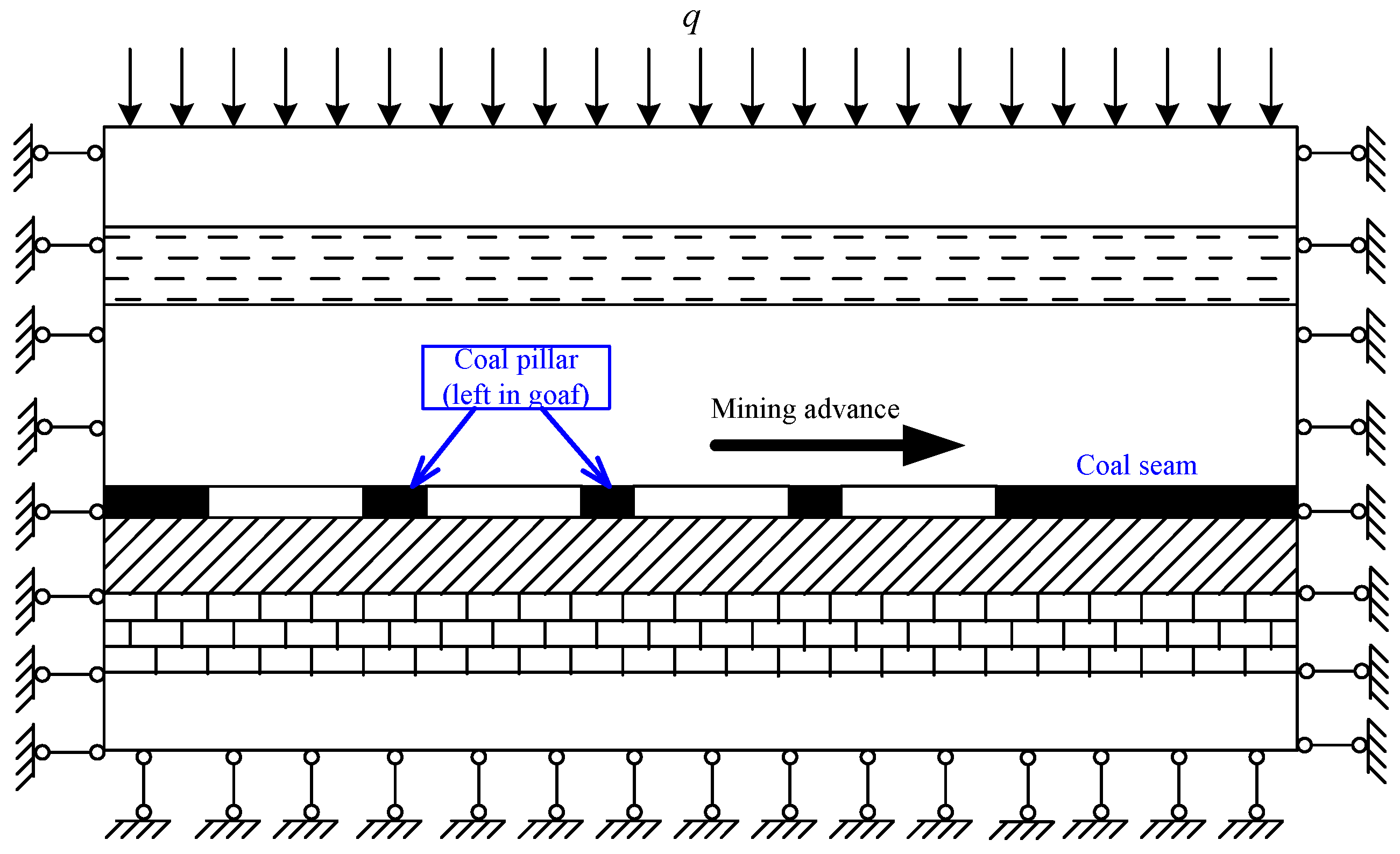
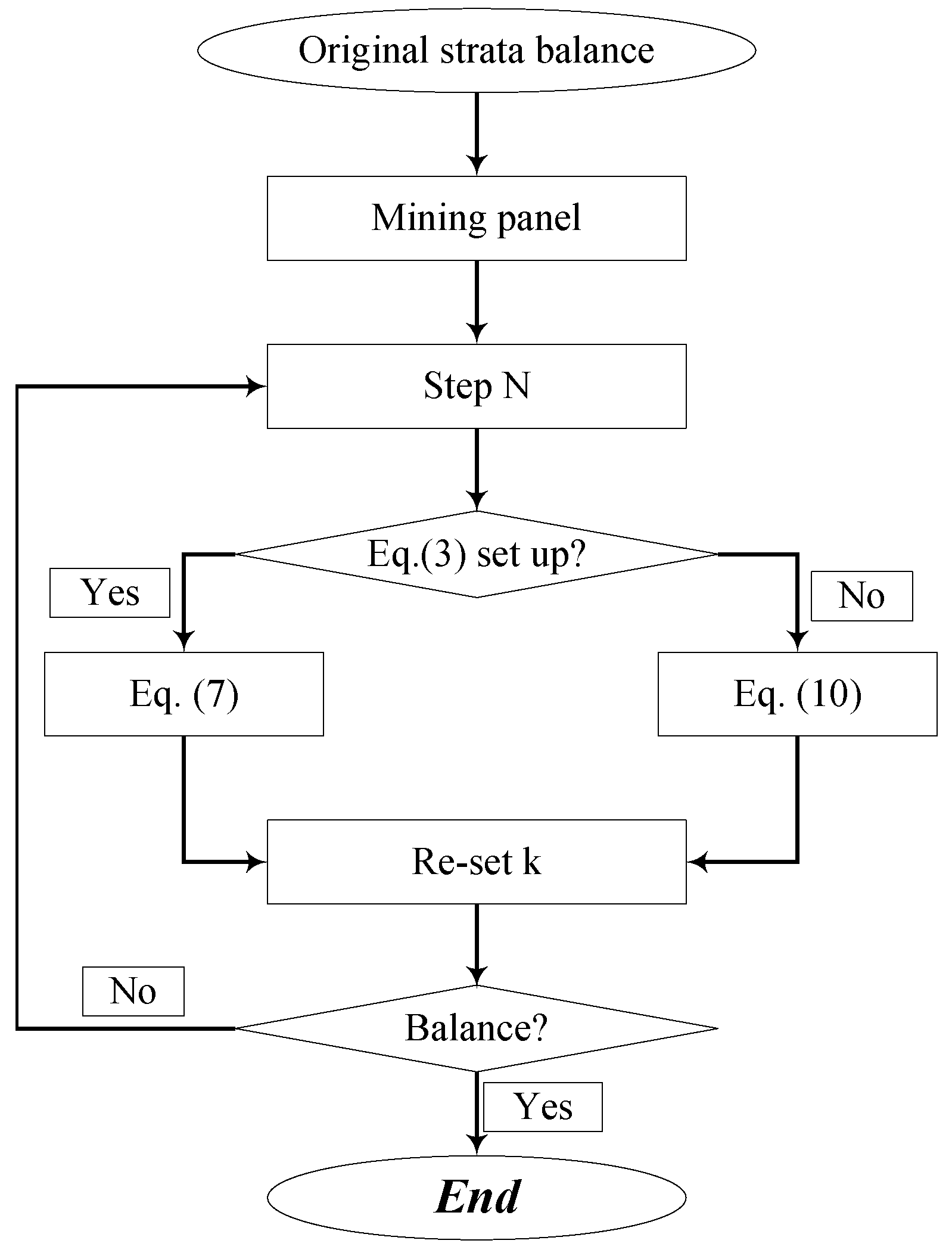
The strain softening model depends on the Mohr–Coulomb failure criterion in FLAC3D with associated tension and nonassociative shear rule, is selected for the criterion of failure of the coal seam model [31,32,33,34]. By applying a proposed piecewise linear function, the friction angle and the cohesion are adapted to intenerate the rocks after the beginning of plastic the yield in this model [35]. These characters are kept to be stable in the standard Mohr–Coulomb model. Table 2 shows the mechanical parameters employed in this simulation for obtaining a reasonable load–deformation relationship. As shown in Figure 8, the boundary conditions of this numerical model are fixed surround the pillar under uniaxial compression. Since the area that is represented by the symmetrical cut is only a quarter of the column, the displacement of the four perpendicular symmetry plains is limited in the normal direction, and a zero vertical displacement situation is fixed on the basis of the model. Here, by addressing FISH language, Equations (1), (3), (7) and (10) are inserted into FLAC3D model. Then, instability properties of a floor-pillar-roof system during mining could be obtained. Figure 9 shows the computing procedure, which means that these models described above are combined with the Mohr–Coulomb failure model in FLAC3D to predict the stress evolution.
The stress distribution of the 211301 panels was numerically simulated by FLAC3D. In the proposed numerical model, width is assumed as 195 m in the strike direction, length as 195 m in the dip direction, and height as 300 m. Figure 10 illustrates the corresponding coal seam design, where the height of the coal seam is simulated as 3 m. The element size of the coal seam is a constant 1.0 × 1.0 × 1.0 m3, whereas the element size of the main-floor and roof is 3.0 × 3.0 × 3.0 m3, the element size of the immediate- floor and roof is 2.0 × 2.0 × 2.0 m3. The roadways are 5 m in width and 3 m in thickness, and coal pillar is 25 m in width. Reasonable boundary conditions are applied to obtain the stress distribution in the panel [36]. Vertical displacement at the bottom of the model is fixed to be zero, and the horizontal displacements of the four vertical plains are limited by the normal direction. Additionally, the vertical load () is adopted to simulate the overburden weight at the top model. According to a large amount of data measured by the geo-stress, the stress coefficients in horizontal plains are all set at 0.8. To model the descending roof during the mining process, the immediate roof and the coal seam are excavated during the modeling process [37,38]. During the mining process, an extremely soft elastic material is used to fill the gob area to roughly model the support capability of the crushed rocks falling from the roof. The rock material has the Poisson ratio of 0.25 and the Young’s modulus of 190 MPa [39].
5.2. Modeling Results
Plastic zone and vertical stress evolution during mining are key factors for the analysis of groundwater inrush risk [6,14]. The mechanical state was calculated with mining advancing 20, 40, 60, 80, 100, 120, and 140 m, respectively.
5.2.1. Plastic Zone Development during Longwall Mining
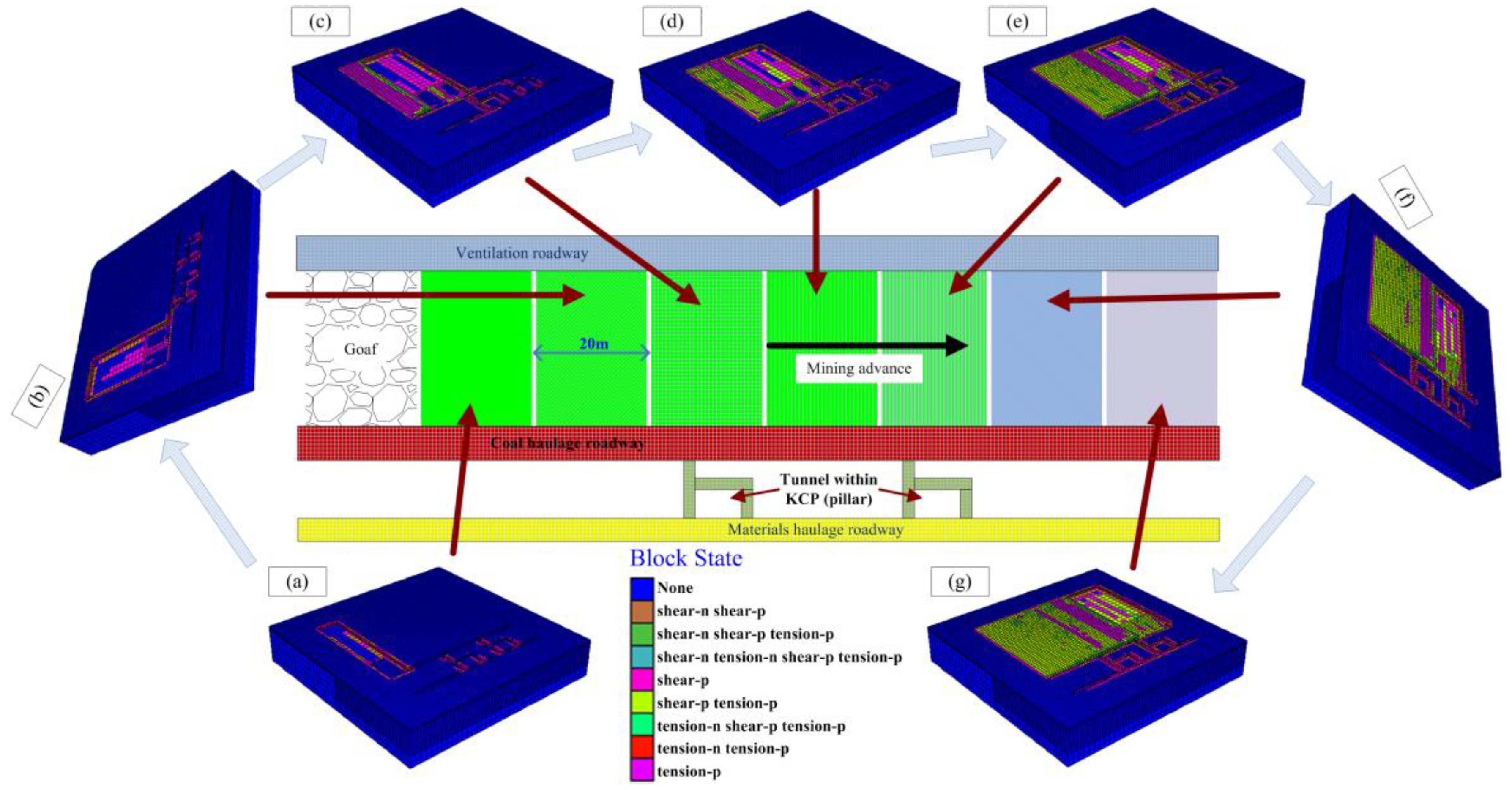
Due to the stress redistribution after mining, a plastic damage zone is formed around the surface in particular. In terms of non-elastic mechanics, the plastic zone in the final case is obviously smaller than that in other cases, and few elements are in the state of shear or tensile failure. As shown in Figure 11, none indicates elastic states of the current rock material, shear-n, shear-p holding the current or the past shear failure states, and tension-n, tension-p holding the current or the past tensile failure states. Figure 12 shows that the plastic damage zone in the coal seam area becomes larger and larger during the mining panel. As the mining distance increases, the plastic zone in the materials haulage roadway also increases.
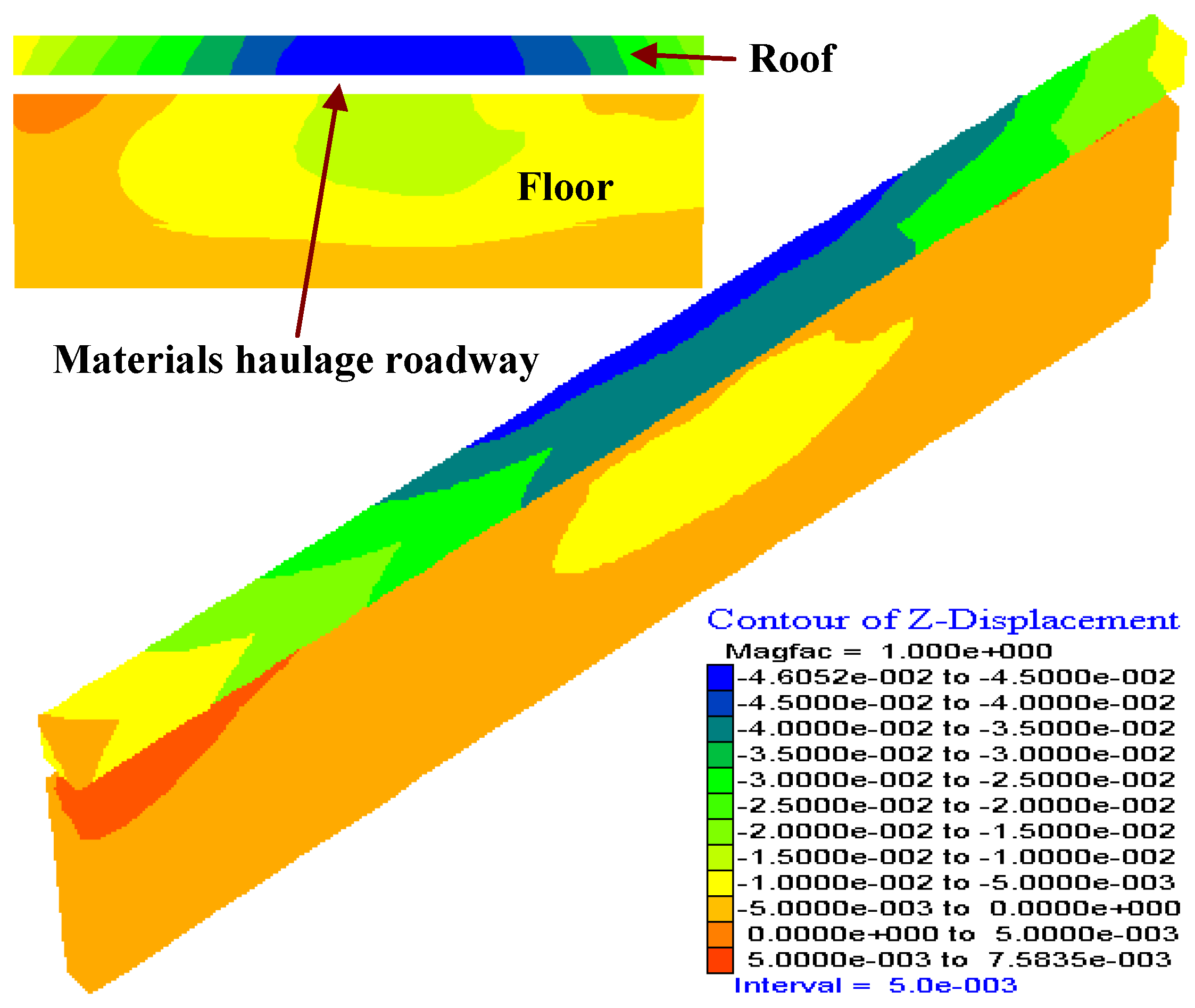
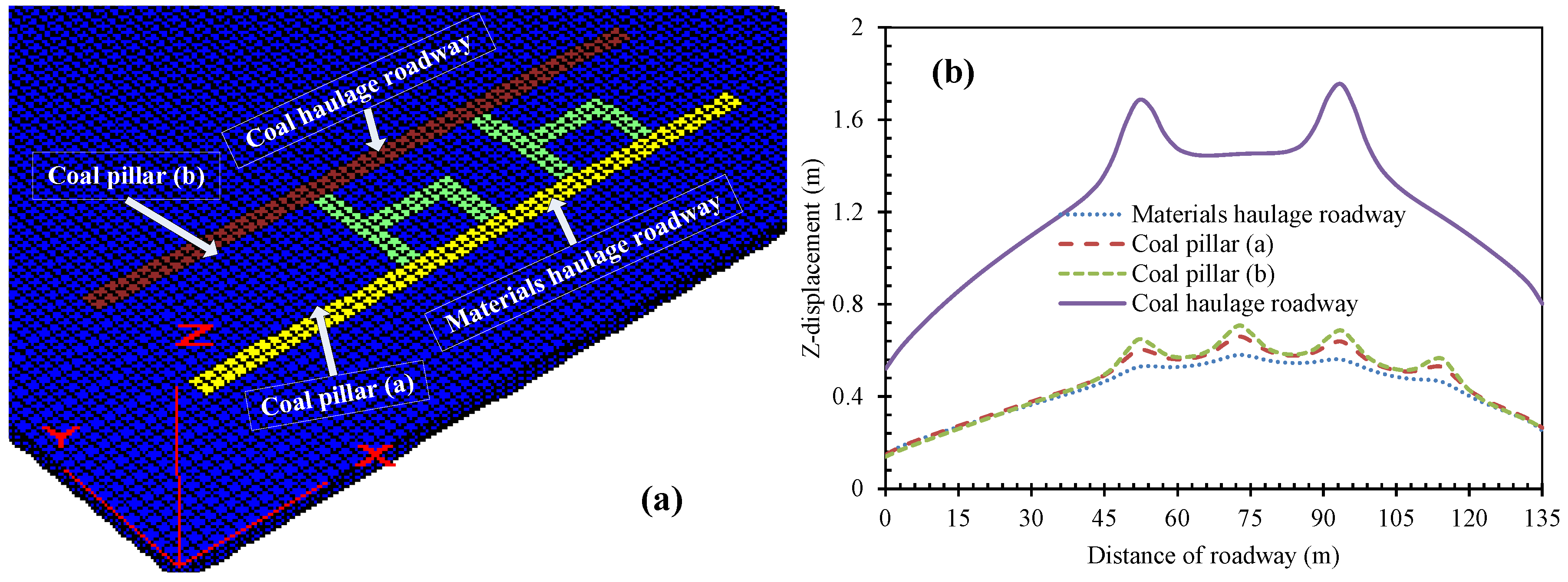
To observe the detailed surface deformation of the roadway roof and floor in the final case (when the mining distance is 140 m), the typical displacement curves of monitoring points are shown in Figure 12 and Figure 13. During iterating computation, these curves vary with surface and monitoring points. During mining, surface deformation of the roadway roof in the tunnel within grouted KCP area are greater than that in two sides, surface deformation of coal haulage roadway roof are greater than that of the coal pillar and materials haulage roadway roof, as shown in Figure 13. It indicates that the coal pillar can protect the deformation of overlying strata. However, the instability causes greater subsidence of overlying strata. Figure 14 shows the subsidence of materials haulage roadway roof with changeable panel distances. It indicates that the surface deformation of the roadway roof increases with the increase of panel distances, especially in the tunneling area within grouted KCP in coal pillar. After the panel, larger displacements occur on larger panel distances, thus enlarging the height of fractured groundwater-conducting zone of overlying strata. If groundwater inrush pathway was connected with the overlying aquifer, the groundwater inrush hazard is easy to occur. Thus, this is a serious threat to groundwater inrush.
5.2.2. Vertical Stress Evolution
To investigate the fracture zone development of the coal face during longwall mining, the typical stress evolution curves of monitoring points are shown in Figure 15. During the iterating computation, the stress evolution is shown when the roadway distance is 140 m. The stress of the coal haulage roadway shows the minimum, which is caused by the protection of coal pillar. Besides, coal pillar protection plays an important role in the decrease of abutment pressure. The stress of coal pillar (b) shows the maximum, even 25 MPa in the tunneling edge within grouted KCP area (peak value), indicating that the line of the pillar supports a big abutment pressure.
Figure 16 shows the representative stress evolution curves for the materials haulage roadway during mining distances from 20 m to 140 m. During the extraction of the mining face, the stress magnitude induced by mining gradually increases. Especially, the stress distribution in the tunnel within a grouted KCP area is more obvious than others.
Numerical results show that the abutment stress reaches a peak at the tunneling edge within grouted KCP area. The length of the influence zone is caused by the mining process. The existence of crushed area (tunnel within grouted KCP) causes coal pillar instability during mining, resulting in the deformation of overlying strata and height enlargement of the fractured groundwater-conducting zone.
6. Conclusions
To investigate the coal pillar instability on groundwater inrush risk from the grouted KCP, an in-situ investigation on the deformation of overlying strata was conducted. A mechanical model for the continuous effect on the coal pillar with the “floor-pillar-roof” system was established, and then a FLAC3D model was also used to simulate continuous instability and groundwater inrush risk from the grouted KCP within a coal pillar in the gob. The following conclusions were obtained.
- (1)
- The collective energy in the “floor-pillar-roof” system is the first criterion for judging the stability of the system. Namely, the larger collective energy in coal pillar than that in floor-roof is the basic factor for the stability of “floor-pillar-roof” system.
- (2)
- The stiffness of the floor-roof and coal pillars is the second criterion for judging the instability of the system. Namely, if any of the stiffness of floor-roof or coal pillar meets a negative value, the system will lose its stability; the groundwater inrush pathway in the grouted KCP will be produced. However, when sum stiffness of “floor-pillar-roof” system meets a negative value, it means that the system structure is situated in a damage state.
- (3)
- A narrower coal pillar enlarges the risk of continuous instability of the system, resulting in the groundwater inrush pathway in the grouted KCP easily. Continuous coal pillars show a lower probability of instability. Conversely, the fractured coal pillars have a greater probability of failure.
- (4)
- The plastic zone and deformation of the roadway roof in the fractured coal pillar are larger than that of continuous coal pillar, indicating that the continuous coal pillar can mitigate the risk of groundwater inrush hazard from the grouted KCP effectively. The results that were obtained in this paper provide a scientific prevention for the groundwater inrush hazard from grouted KCP in practical engineering.
Author Contributions
D.M., X.C. and Q.L. conducted the in-situ investigation; D.M. and X.C. designed the numerical model, performed the simulations and analyzed the data; D.M., Q.L. and H.D. wrote the paper.
Funding
This work was supported by the National Natural Science Foundation of China (51804339). The first author would like to thank the financial supported by the Open Project of Research Center of Coal Resources Safe Mining and Clean Utilization, Liaoning (LNTU17KF03).
Acknowledgments
The authors would like to acknowledge the editor and three anonymous reviewers for their valuable comments, which have greatly improved this paper.
Conflicts of Interest
The authors declare no conflict of interest.
References
- Li, G.Y.; Zhou, W.F. Impact of karst water on coal mining in North China. Environ. Geol. 2006, 49, 449–457. [Google Scholar] [CrossRef]
- Sun, W.J.; Zhou, W.F.; Jiao, J. Hydrogeological classification and water inrush accidents in China’s coal mines. Mine Water Environ. 2016, 35, 214–220. [Google Scholar] [CrossRef]
- Ma, D.; Rezania, M.; Yu, H.S.; Bai, H.B. Variations of hydraulic properties of granular sandstones during water inrush: Effect of small particle migration. Eng. Geol. 2017, 217, 61–70. [Google Scholar] [CrossRef] [Green Version]
- He, K.Q.; Yu, G.M.; Lu, Y.R. Palaeo-karst collapse pillars in Northern China and their damage to the geological environments. Environ. Geol. 2009, 58, 1029–1040. [Google Scholar]
- Ma, D.; Bai, H.B.; Miao, X.X.; Pu, H.; Jiang, B.Y.; Chen, Z.Q. Compaction and seepage properties of crushed limestone particle mixture: An experimental investigation for Ordovician karst collapse pillar groundwater inrush. Environ. Earth Sci. 2016, 75, 11. [Google Scholar] [CrossRef]
- Ma, D.; Miao, X.X.; Bai, H.B.; Huang, J.H.; Pu, H.; Wu, Y.; Zhang, G.M.; Li, J.W. Effect of mining on shear sidewall groundwater inrush hazard caused by seepage instability of the penetrated karst collapse pillar. Nat. Hazards 2016, 82, 73–93. [Google Scholar] [CrossRef]
- Zhang, J.C.; Zhang, Y.Z.; Liu, T.Q. Fluid Flow in Rock Mass and Water In-Rush through Coal Seam Floor; Geology Press: Beijing, China, 1997. (In Chinese) [Google Scholar]
- Zhang, J.C.; Shen, B.H. Coal mining under aquifers in China: A case study. Int. J. Rock Mech. Min. Sci. 2004, 41, 629–639. [Google Scholar] [CrossRef]
- Li, L.J.; Qian, M.G.; Li, S.G. Mechanism of water in-rush through fault. J. China Coal Soc. 1996, 21, 119–123. (In Chinese) [Google Scholar]
- Guo, W.J.; Liu, Y.X. The concept of water in-rush coefficient and its application. Hebei Coal 1989, 2, 56–60. (In Chinese) [Google Scholar]
- Miao, X.X.; Cui, X.M.; Wang, J.A.; Xu, J.L. The height of fractured water-conducting zone in undermined rock strata. Eng. Geol. 2011, 120, 32–39. [Google Scholar] [CrossRef]
- Wu, Q.; Xu, H.; Pang, W. GIS and ANN coupling model: An innovative approach to evaluate vulnerability of karst water inrush in coalmines of North China. Environ. Geol. 2008, 54, 937–943. [Google Scholar] [CrossRef]
- Wu, Q.; Liu, Y.Z.; Liu, D.H.; Zhou, W.F. Prediction of floor water inrush: The application of GIS-Based AHP vulnerable index method to Donghuantuo coalmine, China. Rock Mech. Rock Eng. 2011, 44, 591–600. [Google Scholar] [CrossRef]
- Bai, H.B.; Ma, D.; Chen, Z.Q. Mechanical behavior of groundwater seepage in karst collapse pillars. Eng. Geol. 2013, 164, 101–106. [Google Scholar] [CrossRef]
- Lu, Y.L.; Wang, L.G. Numerical simulation of mining-induced fracture evolution and water flow in coal seam floor above a confined aquifer. Comput. Geotech. 2015, 67, 157–171. [Google Scholar] [CrossRef]
- Wang, J.A.; Park, H.D. Coal mining above a confined aquifer. Int. J. Rock Mech. Min. Sci. 2003, 40, 537–551. [Google Scholar] [CrossRef]
- Zhang, R.; Jiang, Z.Q.; Sun, Q.; Zhu, S.Y. The relationship between the deformation mechanism and permeability on brittle rock. Nat. Hazards 2013, 66, 1179–1187. [Google Scholar] [CrossRef]
- Ma, D.; Zhou, Z.L.; Wu, J.Y.; Li, Q.; Bai, H.B. Grain size distribution effect on the hydraulic properties of disintegrated coal mixtures. Energies 2017, 10, 612. [Google Scholar] [CrossRef]
- Zhang, R.; Jiang, Z.Q.; Zhou, H.Y.; Yang, C.W.; Xiao, S.J. Groundwater outbursts from faults above a confined aquifer in the coal mining. Nat. Hazards 2014, 71, 1861–1872. [Google Scholar] [CrossRef]
- Yin, S.X.; Zhang, J.C.; Liu, D.M. A study of mine water inrushes by measurements of in situ stress and rock failures. Nat. Hazards 2015, 79, 1961–1979. [Google Scholar] [CrossRef]
- Zhang, D.S.; Fan, G.W.; Ma, L.Q.; Wang, X.F. Aquifer protection during longwall mining of shallow coal seams: A case study in the Shendong Coalfield of China. Int. J. Coal Geol. 2011, 86, 190–196. [Google Scholar] [CrossRef]
- Ma, D.; Bai, H.B.; Wang, Y.M. Mechanical behavior of a coal seam penetrated by a karst collapse pillar: Mining induced groundwater inrush risk. Nat. Hazards 2015, 75, 2137–2151. [Google Scholar] [CrossRef]
- Zhang, J.C. Investigations of water inrushes from aquifers under coal seams. Int. J. Rock Mech. Min. Sci. 2005, 42, 350–360. [Google Scholar] [CrossRef]
- Peng, S.S. Longwall Mining, 2nd ed.; West Virginia University: Morgantown, WV, USA, 2006; ISBN 0978938305. [Google Scholar]
- Ma, D.; Cai, X.; Zhou, Z.L.; Li, X.B. Experimental investigation on hydraulic properties of granular sandstone and mudstone mixtures. Geofluids 2018. [Google Scholar] [CrossRef]
- Fleck, N.A.; Hutchinson, J.W. A phenomenological theory for strain gradient effects in plasticity. J. Mech. Phys. Solids 1993, 41, 1825–1857. [Google Scholar] [CrossRef]
- Kaiser, P.K.; Tang, C.A. Numerical simulation of damage accumulation and seismic energy release during brittle rock failure—Part II: Rib pillar collapse. Int. J. Rock Mech. Min. Sci. 1998, 35, 123–134. [Google Scholar] [CrossRef]
- Qin, S.Q.; Wang, S.J.; Long, H.; Liu, J. A new approach to estimating geo-stresses from laboratory Kaiser effect measurements. Int. J. Rock Mech. Min. Sci. 1999, 36, 1073–1077. [Google Scholar] [CrossRef]
- Hoek, E.; Carranza-Torres, C.; Corkum, B. Hoek-brown failure criterion—2002 edition. In Proceedings of the 5th North American Rock Mechanics Symposium, Toronto, ON, Canada, 7–10 July 2002; pp. 267–273. [Google Scholar]
- Hoek, E.; Marinos, P.; Benissi, M. Applicability of the geological strength index (GSI) classification for very poor and sheared rock masses. The case of the Athens schist formation. Bull. Eng. Geol. Environ. 1998, 57, 151–160. [Google Scholar] [CrossRef]
- Zhou, Z.L.; Cai, X.; Ma, D.; Cao, W.Z.; Chen, L.; Zhou, J. Effects of water content on fracture and mechanical behavior of sandstone with a low clay mineral content. Eng. Fract. Mech. 2018, 193, 47–65. [Google Scholar] [CrossRef]
- Fama, M.E.D.; Trueman, R.; Craig, M.S. Two- and three-dimensional elasto-plastic analysis for coal pillar design and its application to high wall mining. Int. J. Rock Mech. Min. Sci. Geomech. Abstr. 1995, 32, 215–225. [Google Scholar] [CrossRef]
- Singh, R.; Sheorey, P.R.; Singh, D.P. Stability of the parting between coal pillar workings in level contiguous seams. Int. J. Rock Mech. Min. Sci. 2002, 39, 9–39. [Google Scholar] [CrossRef]
- Zhou, Z.L.; Cai, X.; Ma, D.; Chen, L.; Wang, S.F.; Tan, L.H. Dynamic tensile properties of sandstone subjected to wetting and drying cycles. Constr. Build. Mater. 2018, 182, 215–232. [Google Scholar] [CrossRef]
- FLAC3D (Fast Lagrangian Analysis of Continua in 3 Dimensions), version 3.1; Itasca Consulting Group, Inc.: Minneapolis, MN, USA, 2006.
- Ma, D.; Miao, X.X.; Wu, Y.; Bai, H.B.; Wang, J.G.; Rezania, M.; Huang, Y.H.; Qian, H.W. Seepage properties of crushed coal particles. J. Pet. Sci. Eng. 2016, 146, 297–307. [Google Scholar]
- Cheng, Y.M.; Wang, J.A.; Xie, G.X.; Wei, W.B. Three-dimensional analysis of coal barrier pillars in tailgate area adjacent to the fully mechanized top caving mining face. Int. J. Rock Mech. Min. Sci. 2010, 47, 1372–1383. [Google Scholar] [CrossRef]
- Jiang, Y.D.; Wang, H.W.; Xue, S.; Zhao, Y.X.; Zhu, J.; Pang, X.F. Assessment and mitigation of coal bump risk during extraction of an island longwall panel. Int. J. Coal Geol. 2012, 95, 20–33. [Google Scholar] [CrossRef]
- Ma, D.; Li, Q.; Hall, M.R.; Wu, Y. Experimental investigation of stress rate and grain size on gas seepage characteristics of granular coal. Energies 2017, 10, 527. [Google Scholar] [CrossRef]
- Wang, H.W.; Jiang, Y.D.; Zhao, Y.X.; Zhu, J.; Liu, S. Numerical investigation of the dynamic mechanical state of a coal pillar during longwall mining panel extraction. Rock Mech. Rock Eng. 2013, 46, 1211–1221. [Google Scholar] [CrossRef]
Figure 1.
Statistics on mine groundwater inrush accidents (2000–2012).

Figure 2.
Granular rocks in the karst collapse pillar (KCP) and groundwater inrush pathway.

Figure 3.
Four zones of strata deformation in longwall mining [24].
Figure 3.
Four zones of strata deformation in longwall mining [24].

Figure 4.
Placement of coal pillars in the gob.

Figure 5.
Layout of site observation.

Figure 6.
The fracture of roadway roof and floor (picture from 24 October 2013).

Figure 7.
A stress mesh model of a floor-pillar-roof system.

Figure 8.
A mechanical model of coal seam longwall mining.

Figure 9.
Computing procedure of the stress evolution.

Figure 10.
Sketch of the fast Lagrangian analysis of continua in three dimensions (FLAC3D) mesh for the coal panel. (a) Main model; (b) Coal seam design.
Figure 10.
Sketch of the fast Lagrangian analysis of continua in three dimensions (FLAC3D) mesh for the coal panel. (a) Main model; (b) Coal seam design.

Figure 11.
Plastic zone development during coal panel. Mining distance: (a) 20 m; (b) 40 m; (c) 60 m; (d) 80 m; (e) 100 m; (f) 120 m and (g) 140 m.
Figure 11.
Plastic zone development during coal panel. Mining distance: (a) 20 m; (b) 40 m; (c) 60 m; (d) 80 m; (e) 100 m; (f) 120 m and (g) 140 m.

Figure 12.
Z-displacement of materials haulage roadway when mining distance 140 m.

Figure 13.
Z-displacement when mining distance 140 m. (a) Position of monitoring points; (b) Displacement of each position.
Figure 13.
Z-displacement when mining distance 140 m. (a) Position of monitoring points; (b) Displacement of each position.

Figure 14.
Subsidence of materials haulage roadway roof with the panel distances changeability.

Figure 15.
Stress evolution for monitoring points.

Figure 16.
Stress evolution of materials haulage roadway during mining distances.


Table 1.
Deformation of overlying strata at site region.
| Distance to Tunnel within Grouted KCP (m) | Width (m) | Height (m) | Actual Area (m2) | Deformation (%) | ||
|---|---|---|---|---|---|---|
| Actual | Deformation | Actual | Subsidence | |||
| 50 | 5.45 | 0.05 | 2.98 | 0.02 | 16.24 | 1.57 |
| 34 | 5.44 | 0.06 | 2.93 | 0.07 | 15.94 | 3.39 |
| 28 | 5.41 | 0.09 | 2.89 | 0.11 | 15.63 | 5.24 |
| 18 | 5.42 | 0.08 | 2.87 | 0.13 | 15.56 | 5.72 |
| 10 | 5.37 | 0.13 | 2.64 | 0.36 | 14.18 | 14.08 |
| −4 | 5.23 | 0.27 | 2.54 | 0.46 | 13.28 | 19.49 |
| −16 | 5.35 | 0.15 | 2.73 | 0.27 | 14.61 | 11.48 |
| −35 | 5.28 | 0.22 | 2.65 | 0.35 | 13.99 | 15.2 |
| −46 | 5.39 | 0.11 | 2.81 | 0.19 | 15.15 | 8.21 |
Note: 1. Width (design) = 5.5 m; Height (design) = 3.0 m; Design area = 16.5 m. 2. Deformation = (Design area − Actual area)/Design area.
Table 2.
Geology parameters of coal seam, roof, and floor strata.
| Strata | Thickness (m) | Density (kg/m3) | Bulk Modulus (GPa) | Shear Modulus (GPa) | Cohesion (MPa) | Friction Angle (°) | Tensile Strength (MPa) |
|---|---|---|---|---|---|---|---|
| Main roof | 30 | 2600 | 23.5 | 13.3 | 3.6 | 37 | 3.2 |
| Immediate roof | 10 | 2500 | 22.7 | 11.7 | 3.1 | 34 | 2.8 |
| Coal seam | 3 | 1500 | 7.1 | 2.5 | 2.5 | 28 | 1.2 |
| Immediate floor | 5 | 2600 | 22.2 | 12.7 | 3.8 | 34 | 3.8 |
| Main floor | 25 | 2500 | 20.1 | 10.9 | 3.5 | 36 | 3.5 |
© 2018 by the authors. Licensee MDPI, Basel, Switzerland. This article is an open access article distributed under the terms and conditions of the Creative Commons Attribution (CC BY) license (http://creativecommons.org/licenses/by/4.0/).
Share and Cite
MDPI and ACS Style
Ma, D.; Cai, X.; Li, Q.; Duan, H. In-Situ and Numerical Investigation of Groundwater Inrush Hazard from Grouted Karst Collapse Pillar in Longwall Mining. Water 2018, 10, 1187. https://doi.org/10.3390/w10091187
AMA Style
Ma D, Cai X, Li Q, Duan H. In-Situ and Numerical Investigation of Groundwater Inrush Hazard from Grouted Karst Collapse Pillar in Longwall Mining. Water. 2018; 10(9):1187. https://doi.org/10.3390/w10091187
Chicago/Turabian StyleMa, Dan, Xin Cai, Qiang Li, and Hongyu Duan. 2018. "In-Situ and Numerical Investigation of Groundwater Inrush Hazard from Grouted Karst Collapse Pillar in Longwall Mining" Water 10, no. 9: 1187. https://doi.org/10.3390/w10091187
Note that from the first issue of 2016, this journal uses article numbers instead of page numbers. See further details here.