Real-Time Integrated Operation for Urban Streams with Centralized and Decentralized Reservoirs to Improve System Resilience


1
School of Civil Engineering, Chungbuk National University, Cheongju 28644, Korea
2
Research Center for Disaster Prevention Science and Technology, Korea University, Seoul 02841, Korea
3
School of Civil, Environmental and Architectural Engineering, Korea University, Seoul 02841, Korea
*
Author to whom correspondence should be addressed.
Water 2019, 11(1), 69; https://doi.org/10.3390/w11010069
Submission received: 4 December 2018
/
Revised: 21 December 2018
/
Accepted: 26 December 2018
/
Published: 2 January 2019
(This article belongs to the Special Issue Recent Advances in the Assessment of Flood Risk in Urban Areas)
Abstract
:Recently, the number of extreme rainfall events has increased because of climate change. The ever-widening impervious area in urban watersheds also continuously augments runoff volume. Most measures to prevent urban inundation are structural, such as the construction, rehabilitation, and replacement of urban drainage facilities. Because structural measures require time and money, nonstructural measures are also required for the efficient prevention of urban inundation. Current operations in Korea focus on the individual operation of urban drainage facilities while neglecting the status of effluent streams. A study on urban drainage facilities that considers the status of urban streams is necessary to improve the operation of drainage facilities in urban areas. A revised resilience index is suggested to evaluate measures. For the historical rainfall event in 2010, the system resilience for current and integrated operations was 0.199 and 0.238, respectively. For the 2011 event, the system resilience for current and integrated operations was 0.064 and 0.235, respectively. The integrated operation exhibited good performance for the 2010 and 2011 events. Based on the results of this study, an operation as a nonstructural measure for the total management of urban areas is proposed. The revised resilience index could support decision-making processes for flood-management plans.
1. Introduction
As the discharge in urban areas has increased because of urbanization, various measures to prevent inundation have been considered. Structural measures focus on expanding the capacity of urban drainage facilities through construction, rehabilitation, and replacement. The construction of additional drainage facilities can be classified as structural because it requires money and time. Nonstructural measures, such as the operation of urban drainage facilities (centralized and decentralized reservoirs) and flooding alerts, are required to maximize the efficient management of these structural measures. In general, the status of urban streams is not considered because urban drainage facilities in Korea are individually operated to prevent urban inundation. The management of urban drainage systems should include all components, such as urban streams, pump stations, and detention reservoirs; however, previous studies did not consider these components. The previous studies focused on the individual real-time control (RTC) and cooperative operation of urban drainage facilities in a single drainage area. The related studies of RTC in urban drainage can be classified into categories of individual operation and cooperative operation in a drainage area, as shown in Table 1.
Most of the studies related to individual operation have been conducted according to the unit time of operation. Individual operation has been suggested for single urban drainage facilities using various techniques [1,2,3,4,5,6,7]. Additionally, individual operation considering structural and other nonstructural measures has been applied to the design and forecasting field [8,9,10,11]. The cooperative operation of a single drainage area has been conducted for reducing the flooding of a city by applying the cooperation of the sewer system and the pump facility in the same drainage area. Cooperative operation with optimization, including single and multi-objective functions, has been applied to urban drainage systems [12,13,14]. Additional approaches for cooperative operation using the urban inundation model and the concept of resilience have been introduced [15,16,17,18].
These operations can be categorized as individual and cooperative operation of urban drainage facilities in a single drainage area. However, the integrated operation of urban drainage facilities has not yet been examined while considering the status of urban streams. Previous literature on RTC in urban drainage systems focused on the prevention of urban inundation. These approaches (i.e., individual operation and cooperative operation in a drainage area) can reduce the damage that urban inundation causes. However, it is difficult for these approaches to respond under extreme and localized torrential rainfall conditions, and they do not consider sustainable urban development in cities. Therefore, this study proposes a new operation approach that considers the overflow in urban streams and the inundation of inland drainage areas simultaneously as well as the improvement of system resilience. Therefore, it is suggested that this integrated operation could reduce inundation and improve resilience in target watersheds. The term “integrated operation” originated from a research project (Development of advanced techniques in combined inland-river systems) that was supported by the Ministry of Land, Infrastructure, and Transport of the Korean government.
In the 2000s, new approaches that considered various models and components were suggested for more sustainable and resilient cities [19,20,21,22]. These studies are based on the resilience of various factors in urban systems and have led to studies on system resilience in civil engineering, many of which have been performed in the field of water resources engineering. Ever since the concept of resilience was applied to water resources, many studies on the resilience of urban drainage systems have been conducted. A system resilience with conceptual framework and global analysis approach has been proposed for urban drainage systems [23,24,25,26,27]. The resilience index in these studies was calculated by comparing normal and extreme rainfall events.
System resilience is the ability of preparation for, reaction to, and recoverability against a system failure that is generated as a malfunction of system components (e.g., the pump and gate in pump stations), and the resilience index indicates system functionality. Therefore, to maintain high system functionality, the system needs to consider system resilience. For example, in urban drainage systems, if 80 out of 100 units of water can be discharged and there are 20 units of flooding volume, the system functionality is 80%. The resilience in urban drainage systems is based on the quantification of the system functionality at each time point. The resilience in urban drainage systems has been proposed in terms of, and quantified by, the rainfall amount, target area, and flooding volume [10].
One resilience index consists of the unit area, the rainfall amount considering the time of concentration, and the flooding volume [16]. Another resilience index consists of the watershed area, the total rainfall amount, and the flooding volume [10]. A drawback of these two indices is that it is difficult to highlight the differences between each value. In the previous indices, the denominator was very large compared with the flooding volume per minute in the numerator. This was because the denominator was multiplied by the rainfall amount considering the time of concentration (or the total rainfall amount) and the unit area (or the watershed area). The fundamental reason for overestimation in these two indices originates from the rainfall amount in the denominator. The duration for calculating the rainfall amount at each time point is longer than the duration of the flooding volume at each time point. If the flooding volume occurs at 60 min and the time of concentration is 30 min, the rainfall amount is calculated as the sum of 30 min to 60 min (or 1 min to 60 min). The calculation of the rainfall amount needs to be improved.
The revised resilience index can better reflect the status of urban drainage systems. It is calculated using real-time rainfall data and is easy to apply. Various conditions, such as flooding in times of no rainfall and no flooding during rainfall events, can now be considered. A revised resilience index is needed to overcome the disadvantages of the previous indices.
2. Materials and Methodologies
2.1. Integrated Operation Considering Urban Streams
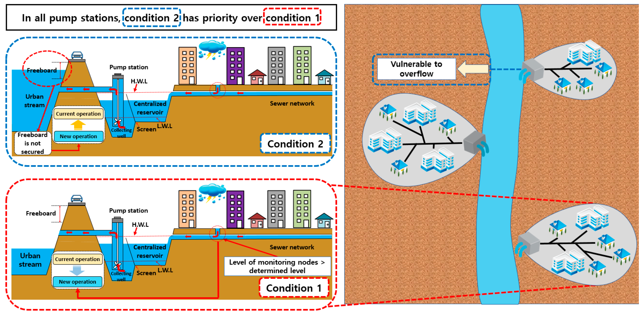
The operation of pump stations should be integrated considering the levels of monitoring nodes and urban streams within the target watershed. RTC in this study means the operation/control of urban drainage facilities considering real-time rainfall data per minute. This approach was applied to each drainage area. Monitoring nodes were selected using the method described by Lee et al. [16], and integrated operation was based on the level of urban streams. When the stream level is high, the freeboard of levees on one or both sides may not be enough to prevent flood risk. In this case, pump stations on the stream do not operate drainage pumps as early as expected; however, they reserve a certain amount of water as the operating level in the centralized reservoirs (CRs) of the pump station increases. The CR in urban drainage systems is located in the downstream of the network in a single drainage area. It receives all inflow from the network, and the inflow in the CR is discharged by drainage pumps in pump stations.
The objective of integrated operation in urban areas is to ensure rapid and safe drainage and to secure additional storage capacity. In addition, it can prevent the backwater effect that is caused by high water levels in the CR and reduce the risk of overflow in urban streams. Moreover, this operation system allows for the effective management of urban streams when the system does not have sufficient capacity. This study looks at the development of an integrated operation system considering sustainable urban management, which applies the revised system resilience index and focuses on Korean urban areas. In Korea, it is difficult to expand the width of streams or increase the height of levees because the tops of levees are used as roads. The integrated operation can balance the spare capacity between urban drainage facilities and urban streams. A schematic of the integrated operation is shown in Figure 1. The proposed approach consists of three schemes: (1) integrated pump operation, (2) the revised system resilience index, and (3) the selection of monitoring nodes.
2.2. Integrated Pump Operation
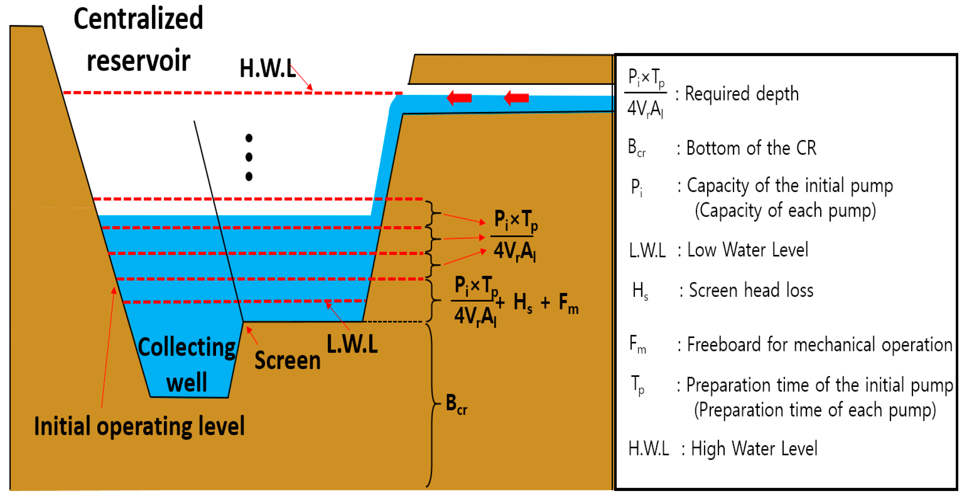
The operation of pump stations in Korea is determined by the level of the CR. The initial CR operating level (Oi) is calculated as the sum of the required depth, screen head loss (Hs), and freeboard for mechanical operation (Fm). Vr is the value of the product of the initial pump capacity and pump preparation time (Tp). The value of Hs varies from 0.1 m to 0.3 m, and the value of Fm varies from 0.0 m to 0.2 m. Hs is determined by the presence or absence of a CR in pump stations, and Fm by the total pump capacity. Both should be determined to prevent the cavitation of drainage pumps. These three factors are added to the bottom of the CR (Bcr) to give the initial operating level of drainage pumps (Oi). Other operating levels, except for the initial operating level, are based on the calculation of the required depth. Early operating levels in each pump station are calculated using the method of Lee et al. [16]. Equation (1) is used to calculate the initial operating level of the drainage pumps in the CR.
where Oi is the initial operating level of the drainage pumps in the CR, Pi is the capacity of the initial pump, Tp is the preparation time of the initial pump, Vr is the required volume in the CR, Al is the average area at each elevation in the CR, Hs is the screen head loss, Fm is the freeboard for mechanical operation, and Bcr is the bed elevation of the CR. Figure 2 shows the determination of operating levels for drainage pumps in CRs.
As the local government in Korea has already determined the operating order for all pump stations, the new operation in the CR has the same operating order as the current one. Pump operation should be determined by operating level and order, considering the cavitation of drainage pumps. When the level of a monitoring node reaches a determined level for a new operation, drainage pumps in the CR are operated early. The operation of the decentralized reservoir (DR) is applied to the integrated operation if there is a DR in the drainage area. The DR’s operation is also based on the level of the monitoring nodes. Pumps in the DR are operated until the level of the monitoring node reaches the operating level of the CR. Lee et al. [16] suggested the cooperative operation of the CR and DR, which means the combined operation of the CR and the DR. In this study, we propose an integrated operation for urban streams with all drainage facilities, including the CR and the DR.
2.3. Revised Resilience Index
Resilience is the ability to recover from a failure because of internal and external shocks to a community system. It involves the ability to recover from flooding or a malfunction of drainage facilities in urban drainage systems. Recently, the concept of resilience has been used in the evaluation of various systems, including future strategies by governments, academia, and enterprises. Todini [28] applied the resilience index to the design of a looped water distribution network using a heuristic approach. A framework to quantitatively assess the improvement in a community’s resilience to seismic hazards was developed by Bruneau et al. [29]. Godshalk [30] recommended constructing resilient cities to withstand the threats of natural hazards and terrorism.
Structural and functional resilience indices in urban drainage systems were suggested in [25,26]. These consist of the total flood volume, the total inflow into the system, the mean duration of nodal flooding (computed for all flooded nodes in the system), and the maximum nodal flood duration or total elapsed time (simulation time). The resilience index in the two studies is the computed design functional resilience index for the design of urban drainage systems. It is not based on real rainfall but on rainfall scenarios. In addition, its application is very complicated because it requires the estimation of the areal reducing factor. Lee et al. [10] introduced the resilience index for urban drainage systems, which is based on the flooding volume per minute, the area of the target watershed, and the total rainfall amount. In this index, the flooding volume has a low impact if the area of the target watershed and the total rainfall amount are large. All values of the resilience index in the previous study are close to 1; therefore, it is difficult to see a difference between current and new measures. In this study, a revised resilience index is introduced to overcome this difficulty.
The main difference between the previous and revised resilience indices lies in the calculation of the denominator in the performance evaluation function. In the previous resilience index, the total rainfall amount is applied to the denominator, while in the revised resilience index, the rainfall amount at each minute is applied to the denominator. The value of the denominator in the previous resilience index is larger than that in the revised resilience index. In addition, these values are classified into various cases because the denominator cannot be calculated when the rainfall amount is zero in the revised resilience index. The revised resilience is calculated as 1 when the rainfall amount and flooding volume are zero. The revised resilience is calculated as 0 when the rainfall amount is zero and the flooding volume is not zero. The rainfall amounts in both resilience indices are different, even though the performance evaluation function is calculated every minute in both. The total amount of rainfall in the watershed is used in the previous resilience index, while the current rainfall amount in the watershed is used in the revised one. The resilience index comprises the performance evaluation function, which is shown in Equation (2):
where u(T)t is the performance at time t, Ft (in m3) is the flooding volume at time t, Rt is the rainfall amount (in m) at time t, and A is the area of the target watershed (in m2). If the value of the performance evaluation is 1, then there is no flooding. Table 2 categorizes the value of utility performance according to the numerator and denominator of Equation (2). In the revised index, the duration of failure is calculated in the equation for resilience because the performance evaluation function is estimated at each minute and the equation for resilience is based on the value of the performance evaluation function.
The sum of the numerators at each time point gives the total flooding volume in the target watershed, and the sum of the denominators at each time point gives the total rainfall amount. The resilience in the target watershed is calculated by the value of the performance every minute. The equation for resilience is shown in Equation (3).
where Rs is the resilience in the target watershed, and T is the entire duration of the rainfall event. The revised resilience index can be calculated for and applied to all watersheds.
2.4. Selection of Monitoring Nodes
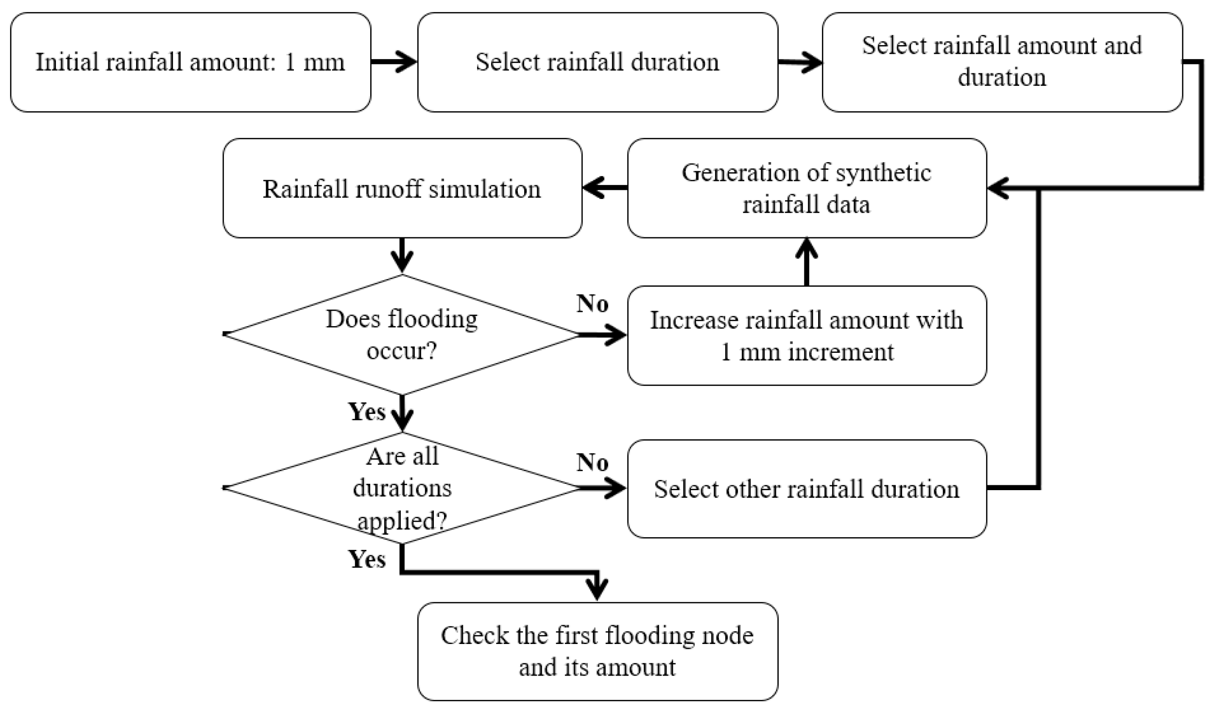
Monitoring nodes are points where inundation first occurs within an urban drainage system [10,16]. Three synthetic rainfall durations were selected on the basis of the time of concentration (tc) (e.g., tc, 2tc, and 3tc).
Time of concentration was used as a variable to allow for a sufficient duration of rainfall to be simulated considering the total amount of rainfall in the drainage system. Additional durations, up to three times as long as the time of concentration, were selected to simulate longer-duration rainfall events. For example, if the time of concentration is 30 min, the three durations are 30, 60, and 90 min. Initially, 1 mm of synthetic rainfall data were produced. This was then increased in 1-mm increments until the first flooding event occurred. The process for finding the first flooding nodes is shown in Figure 3.
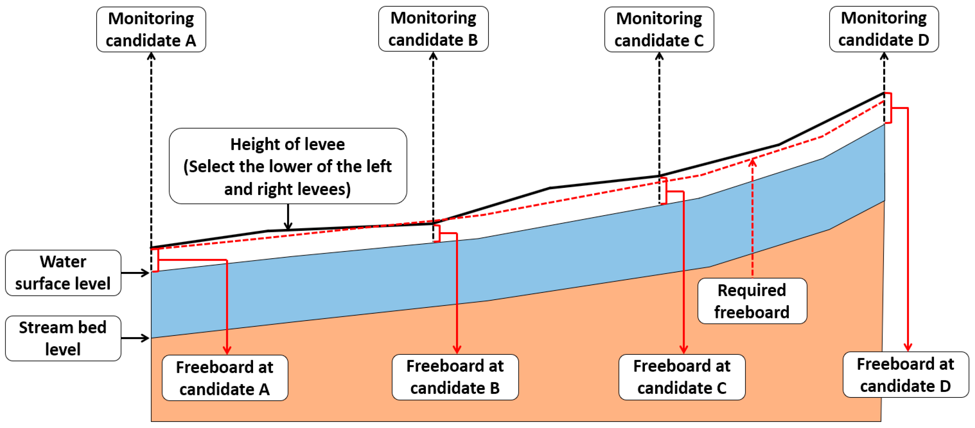
A report detailing the design of discharge in streams in Korea is available to the public [31]. Most streams in Korea have several monitoring nodes under bridges. Monitoring nodes for integrated operation can be selected from among these. Various discharges for each frequency can be applied to the selected simulation model, and the freeboards for each monitoring node can be checked. The monitoring node with the smallest value of freeboard is then selected for use in the integrated operation. The schematic of the monitoring nodes in streams for integrated operation is shown in Figure 4.
In Figure 4, among the four candidates, candidate B can be selected as the monitoring node because the freeboard at candidate B is smaller than the required freeboard. The candidate with the largest difference is selected if the freeboard at several candidates is smaller than the required freeboard. In Korea, monitoring candidates are generally located on bridges, and the required freeboard at each station of streams is determined by the design frequency. The required freeboard of the stream is high if the design frequency of the stream is high. For example, the required freeboard of the stream is 0.6 m for a 100-year frequency, and the required freeboard is 0.8 m for a 200-year frequency. The design frequency of the downstream is larger than that of the upstream if the design frequencies of the upstream and downstream are different.
2.5. Model Formulation
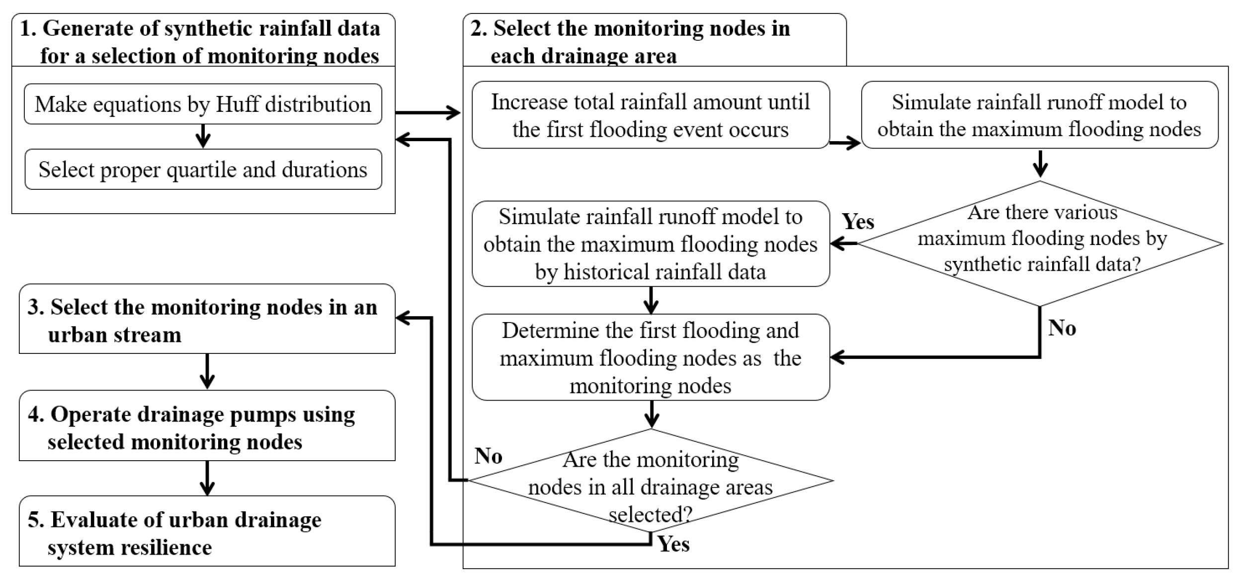
This study consisted of five parts, as shown in Figure 5. First, synthetic rainfall data were generated for the selection of monitoring nodes. Second, monitoring nodes in each drainage area were selected to operate drainage pumps in the CR. Third, a monitoring node in an urban stream was selected for integrated operation in each CR. Fourth, the integrated operation of pump stations was conducted using the level of a monitoring node in an urban stream. Finally, a revised resilience index was suggested and applied to urban drainage systems in a target watershed.
A storm water management model (SWMM) was used for the rainfall runoff simulation of the target watershed [32]. Evaporation and losses can be simulated in the SWMM. In Korea, the evaporation data are generally provided per month and not per minute. Monthly averages in evaporation can be applied to the SWMM, which is only used during dry periods. For infiltration among losses, Horton’s infiltration equation was used. Each parameter was changed during calibration. Other losses were considered using the percentage of impervious area at each sub-catchment.
2.6. Study Area
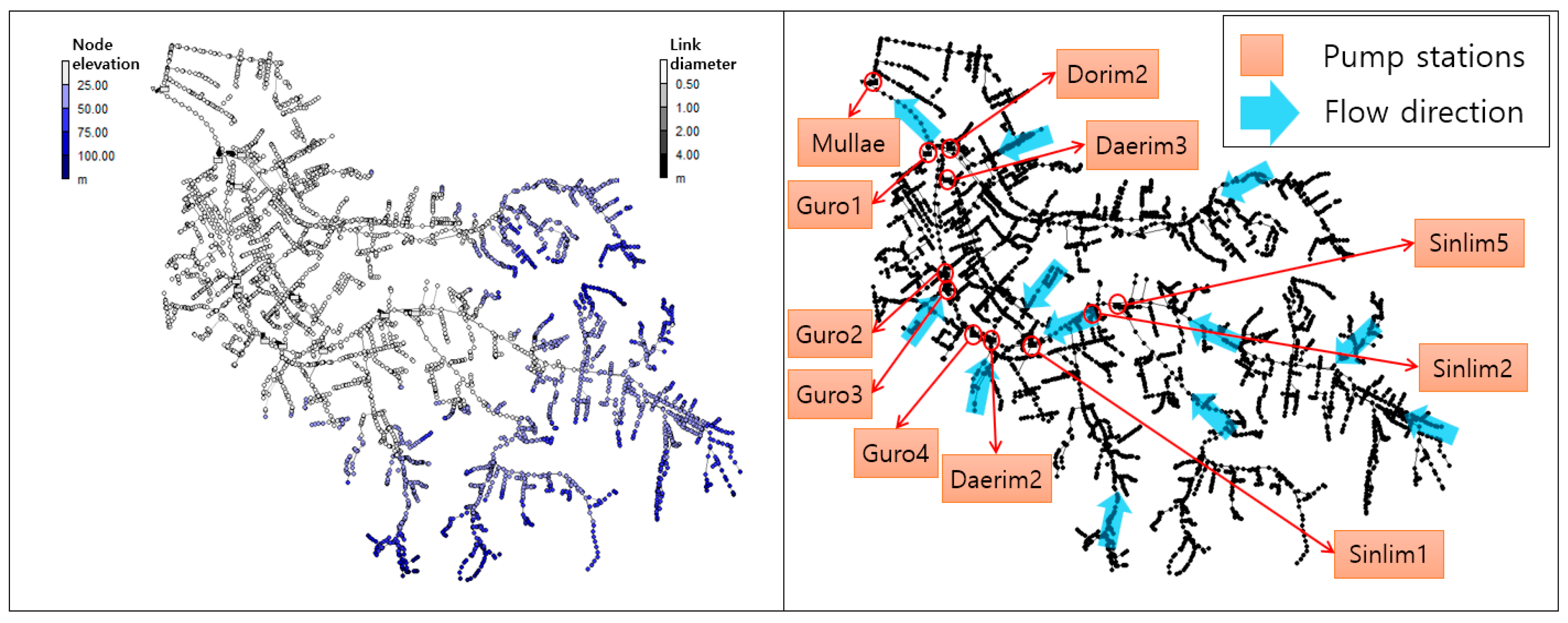
The Dorim stream was selected as the target watershed, and is shown in Figure 6. It has a total area of 41.93 km2. Furthermore, there are 11 pump stations (Mullae, Dorim2, Daerim3, Daerim2, Guro1, Guro2, Guro3, Guro4, Sinlim1, Sinlim2, and Sinlim5), two detention reservoirs (Daerim and Gwanak), and two branches (the Daebang and Bongchun streams) along the stream.
The characteristics of Dorim stream consist of river length, levee length, mean width of basin, shape factor, and slope. Among them, the mean width of basin is the value of area (A) divided by the river length (L) and the shape factor is the value of area (A) divided by the square of river length (L). Table 3 shows the characteristics of the Dorim stream [31].
A rainfall station is located in the center of the target watershed. Table 4 provides information on the pump stations in the target watershed, including CR capacity, drainage pump capacity, drainage area, high water level (HWL), and low water level (LWL) [33,34,35,36,37,38,39,40,41,42,43,44].
The total drainage area of the 11 pump stations is 884 ha (8.84 km2), which is approximately 21% of the total drainage area of the Dorim stream. The Daerim detention reservoir was constructed in 2009 and the Gwanak detention reservoir in 2016. They are described in Table 5 [45,46].
Inundations occurred at the Dorim stream in 2010 and 2011. The total annual precipitation in 2010 was 2.075 mm, and the total amount of rainfall was 253 mm when the flooding occurred on 21 September 2010. The total annual precipitation in 2011 was 2.014 mm, and the total amount of rainfall was 378 mm when the flooding occurred on 27 July 2011 [47]. These historical rainfall events have a frequency of approximately 100 years, which is greater than the design frequency of the urban drainage facilities [47,48].
The new model of the sewer network in the target watershed is based on the geographic information system data for urban drainage areas and streams supplied by the Seoul Metropolitan Government. Figure 7 shows the digital elevation model, hill shade, slope, and aspect of flow direction in the target watershed [45].
As shown in Figure 8, the sewer network in the target watershed consists of 4137 sub-catchments, 4544 nodes, and 4710 links.
2.7. Generation of Synthetic Rainfall Data
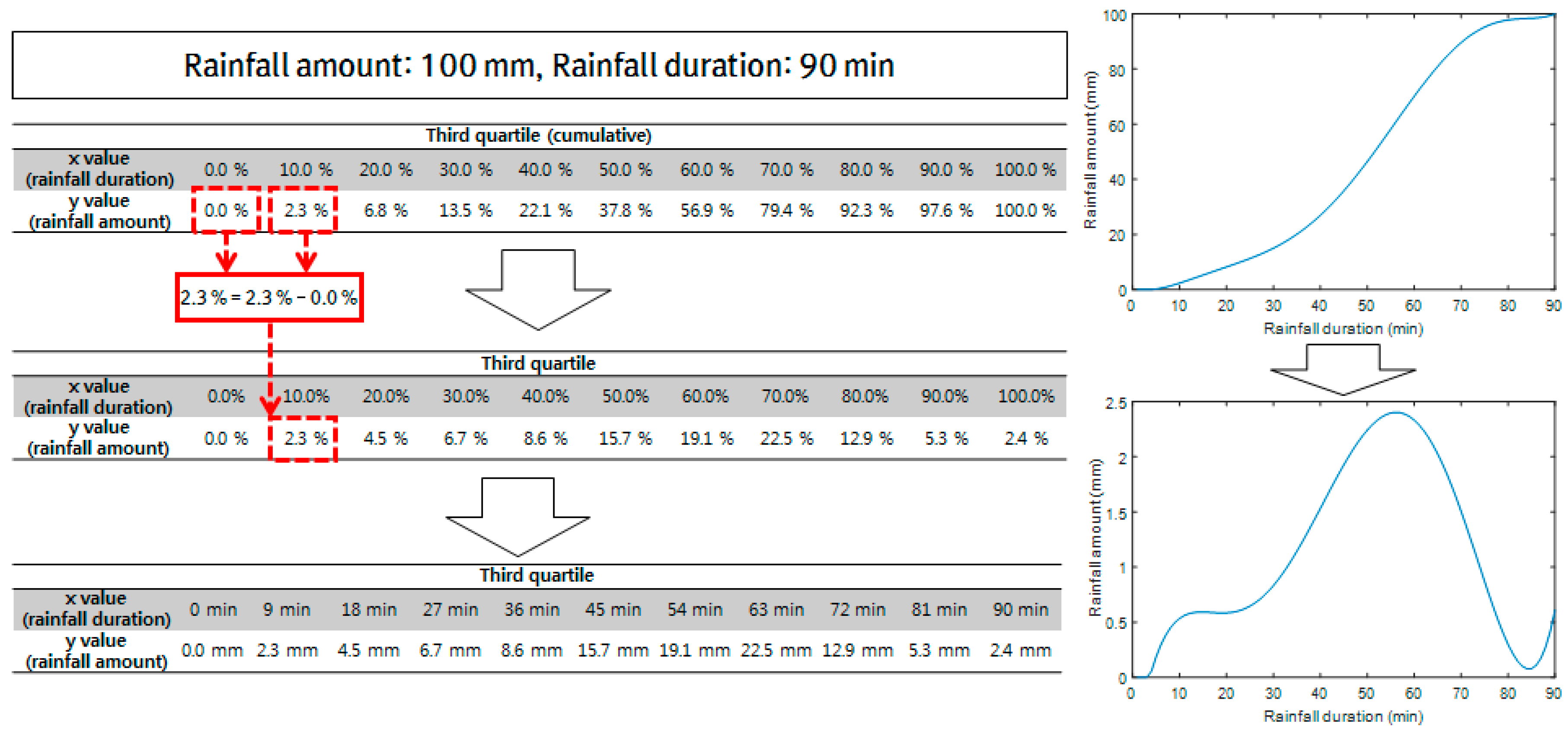
For each drainage area and urban stream, synthetic rainfall data were generated using the Huff distribution [49], and monitoring nodes were selected by means of a rainfall runoff simulation. The synthetic rainfall data were used for the selection of monitoring nodes, and the historical rainfall data were selected to verify the effect of the integrated operation. The Huff distribution was used because its third quartile is appropriate for the design and operation of drainage facilities in Korea [50]. The design of Korean urban drainage facilities is based on this distribution. Equation (4) shows the regression equation for the third quartile of the Huff distribution in Seoul [51].
where y is the ratio of cumulative rainfall, and x is the ratio of the total rainfall duration. The process of generating synthetic rainfall data from the Huff distribution consists of three steps. First, a cumulative distribution is generated using the regression equation of the Huff distribution. Second, the separated ratio is produced by the cumulative distribution. Third, the rainfall amount and duration are applied to the separated ratio [51]. This process is illustrated in Figure 9.
Moreover, the sewer network in the target watershed was manually calibrated using the 2010 and 2011 rainfall events. After the calibration of each sub-watershed in each CR, the total runoff was calibrated downstream of each drainage area. The peak discharge, peak time, total runoff volume, and minimization of the root mean square error were focused on the calibration of the model. The percentage of impervious area, width, and percentage of slope in each sub-catchment were used to calibrate the model. In addition, the maximum infiltration rate, minimum infiltration rate, and decay constant in Horton’s infiltration equation were used to calibrate the model.
3. Application and Results
3.1. Selecting Monitoring Nodes in Each Drainage Area and Stream
The selection of monitoring nodes is required for the integrated operation of drainage facilities, such as a CR and a DR. This is because a CR’s operation, or a cooperative operation between a CR and a DR, is based on the level of monitoring nodes. In this study, monitoring nodes were selected using two methods, based on the first flooding node and the maximum flooding node.
The first flooding node generally occurs between branch conduits, rather than between main conduits. This makes it difficult to use for the integrated operation of drainage facilities. A section is categorized as the main conduit based on the product of the runoff coefficient (C) and drainage area (A). If this is greater than 0.12 km2 (CA ≥ 0.12 km2), then it is the main conduit. If it is smaller than 0.12 km2 (CA < 0.12 km2), then it is a branch [16]. The first flooding node is selected using the results of rainfall runoff simulations, with synthetic rainfall events generated by the Huff distribution. The amount of synthetic rainfall is increased from 1 mm in 1 mm increments, and this is applied to the runoff model until the first flooding event occurs. The first flooding nodes in each drainage area are shown in Table 6.
The rainfall amount required to cause the first flood of the drainage system in the Daerim3 pump station is higher than that in the others. This means that the drainage system in the Daerim3 pump station is relatively strong against initial flooding. Conversely, the drainage systems in the Sinlim1, Sinlim2, and Sinlim5 pump stations are relatively weak against initial flooding. Some drainage areas have different first flooding nodes for different rainfall durations. The drainage areas in Guro1, Dorim2, and Daerim3 show different first flooding nodes at 90 min because some conduits in these areas have reverse gradients, causing different initial flooding patterns. However, the Guro2, Guro3, Guro4, Guro4, Sinlim1, Sinlim2, Sinlim5, Mullae, and Daerim2 pump stations all demonstrated the same first flooding node for all durations. When a drainage area had different first flooding nodes at 90 min, the node that appeared in the largest number of results was selected.
The maximum and first flooding nodes were selected as the monitoring nodes for the integrated operation in each drainage area. To select the maximum flooding nodes, historical rainfall events were used, rather than synthetic ones, as simulations using synthetic rainfall events produce various maximum flooding nodes, making the selection of monitoring nodes difficult. Rainfall data from 23 September 2010 and 27 July 2011, when historical flooding occurred in the target watershed, were used to identify the maximum flooding nodes in each drainage area. The maximum flooding nodes in each drainage area are shown in Table 7.
Several maximum flooding nodes demonstrated a greater flooding volume than those in other drainage areas, namely Sinlim1, Sinlim2, Sinlim5, Mullae, and Dorim2. This is because of the capacity shortage of conduits and backwater effects produced by the level of the CR. A single node is selected as a monitoring node if the first flooding node is the same as the maximum flooding node. Two nodes are selected as monitoring nodes if the two are different. In the real-time integrated operation, Guro1, Guro3, Guro4, Sinlim1, Sinlim5, Mullae, Daerim2, and Daerim3 each have two monitoring nodes, while Guro2, Sinlim2, and Dorim2 have one. If the depths of the two monitoring nodes differ, they are converted into a dimensionless parameter. The depth of the monitoring node is converted to 1.0D if it is 1.5 m, and the level is converted to 0.6D if it is 0.9 m.
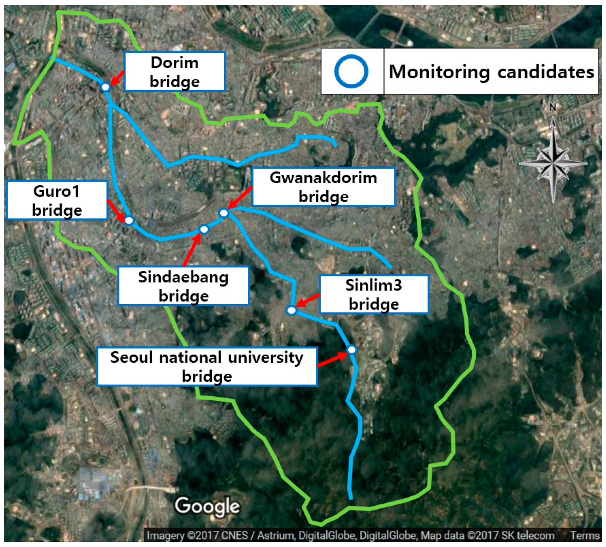
In Korea, monitoring nodes in urban streams are constructed under bridges. There are six bridges across the Dorim stream: the Dorim, Guro1, Sindaebang, Gwanakdorim, Sinlim3, and Seoul National University Bridges. All streams in Korea have a designed freeboard, and this is 0.6 m for the Dorim stream. The monitoring candidates in the Dorim stream are shown in Figure 10.
Rainfall events with various frequencies (30, 50, 80, 100, and 200 years) and with a duration based on the time of concentration in the Dorim stream (360 min) were applied to select the monitoring nodes. The water level in the Dorim stream, height of the bank, and freeboard for events with 30-, 50-, 80-, 100-, and 200-year frequencies are shown in Table 8.
For the 30-year frequency, all monitoring candidates satisfy the designed freeboard of the Dorim stream. For the 80- and 100-year frequencies, the right bank at Sindaebang Bridge lacks a freeboard. Overflow occurs here with a 100-year frequency. The other monitoring candidates satisfy the designed freeboard of the Dorim stream. However, the banks of various monitoring candidates, such as the left bank at the Dorim Bridge, both banks at the Sindaebang Bridge, and the right bank at the Sinlim3 Bridge, also lack a freeboard. Overflow occurs at the right bank at the Sindaebang Bridge, and the overflow from a 100-year frequency event is the same as that for an 80-year frequency event. Both banks at the Dorim, Sindaebang, and Gwanakdorim Bridges, and the right bank at the Sinlim3 Bridge, also lack a freeboard. Overflow occurs at the Dorim and Sindaebang Bridges. The results in Table 8 shows that overflows at Sindaebang Bridge occur with 80-, 100-, and 200-year frequencies. This section of the Dorim stream is most vulnerable to overflow.
3.2. Results of the Rainfall Runoff Simulation
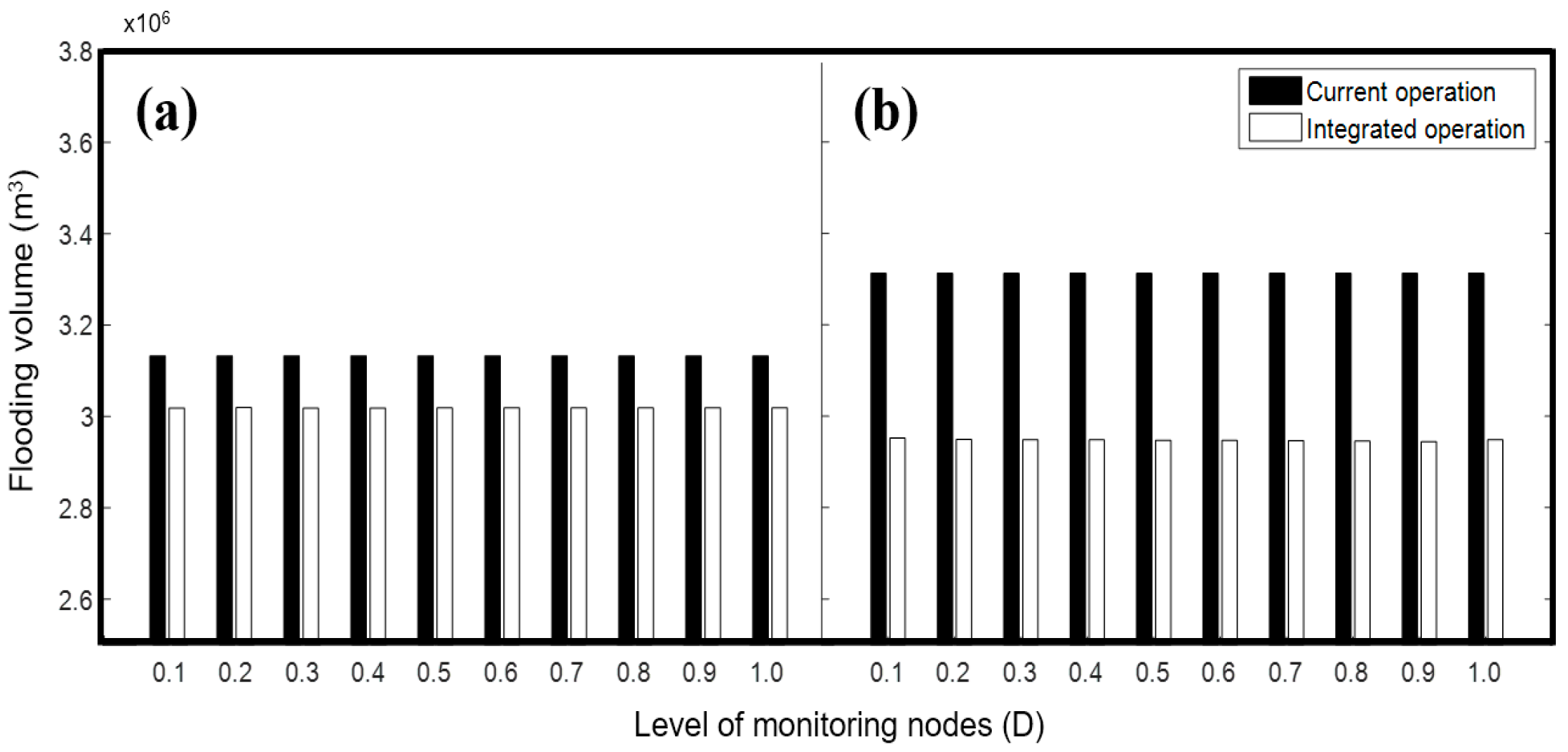
Historical rainfall events in 2010 and 2011, when flooding occurred in the Dorim stream, were selected for the rainfall runoff simulation, in which the current and integrated approaches for operating drainage facilities, including CR and DR operations, were applied to the target watershed. The integrated operation, which includes the use of the CR, was applied to each pump station in the Dorim stream. The preparation time was between 5 and 30 min. The calculation was used to determine the initial operating level in the CR. This was applied to the Daerim3 pump station as follows. The product of the initial pump discharge (233 m3/min) and the preparation time (30 min) were divided by 4. The required volume in the CR was 1711 m3 and the average area at each elevation in the CR was 11,400 m2. The required depth was calculated by dividing the required volume in the CR by the average area at each elevation [16]. Table 9 shows the operating levels of the drainage pumps in each drainage area of the Dorim stream.
These data are shown for both the integrated and current operations. The results, shown in Figure 11a, indicate that the integrated operation produces a lower flooding volume than the current operation (which produces 2,905,874 m3).
Overall, the integrated operation demonstrated good results, although they varied slightly according to the operating levels. When the level of the monitoring node was 0.2D, the maximum flooding volume was 2,743,103 m3, and the minimum flooding volume was 2,741,478 m3 with a level of 0.3D. Figure 11b shows the results of the current and integrated operations for 2011. The results in Figure 11b also show that the integrated operation produced a lower flooding volume than the current operation (3,312,733 m3) for all levels of the monitoring node. The integrated operation once more showed good results, although they still slightly differed from one other according to the operating levels. The maximum flooding volume was 2,951,973 m3 when the level of the monitoring node was 0.1D, and the minimum flooding volume was 2,944,196 m3 when the level was 0.9D. The results of Figure 11 show that the integrated operation was steadily better than the current operation at all levels of the monitoring nodes.
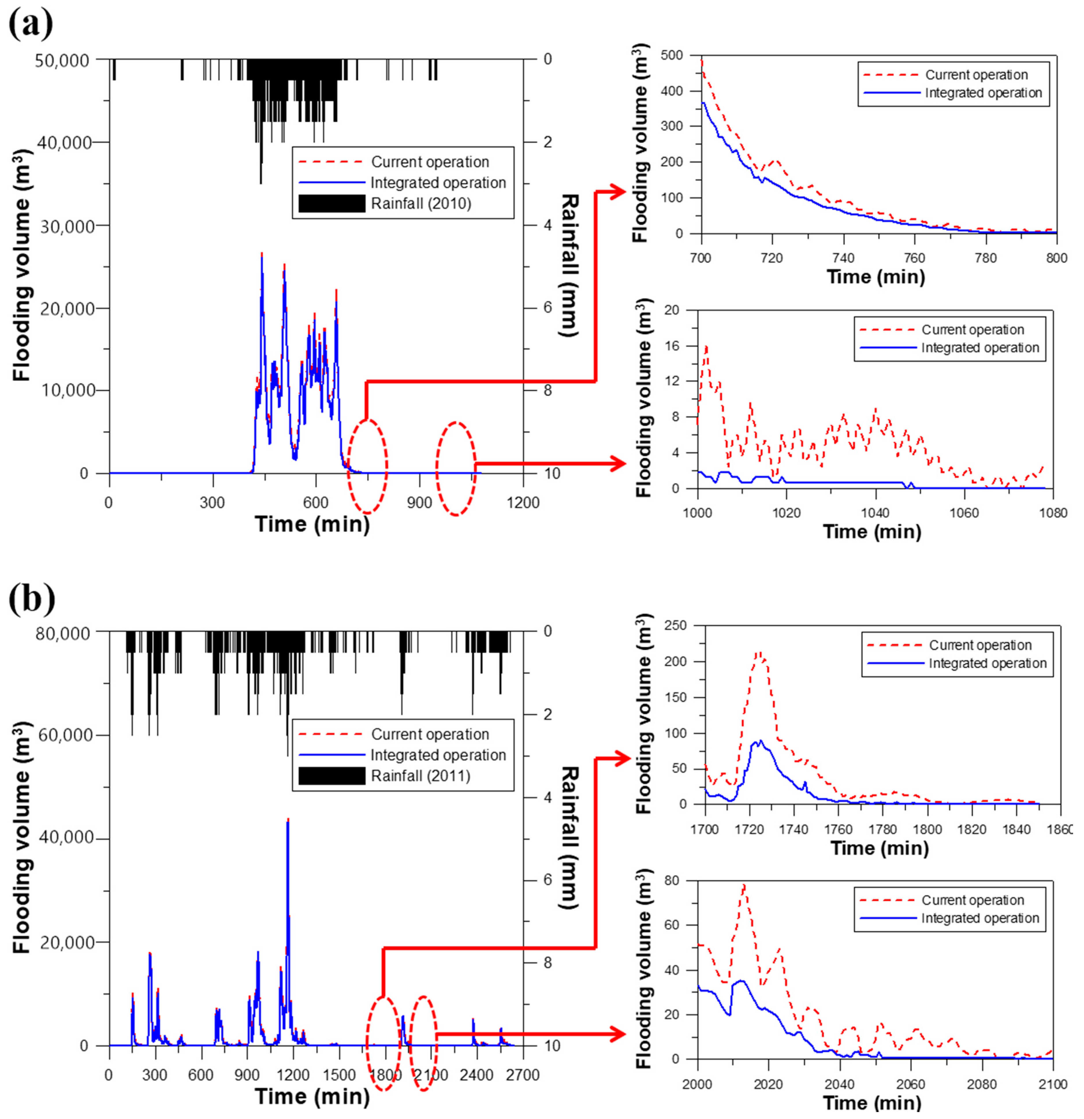
In Figure 12, the results of flooding volume over time using the integrated operation and current operation are compared. The results in 2010 and 2011 are shown in Figure 12a,b, respectively. The results in 2010 and 2011 show that the integrated operation had less flood volume per minute than the current operation.
Moreover, this study applied the system resilience to verify the ability to prepare for and recover from the malfunction (failure) of drainage facilities and inundation (system degradation) of drainage systems. The proposed resilience index was applied to the current and integrated operations for the 2010 and 2011 events. The results of the two operations were compared for both years, when the level of the monitoring node at the beginning of the integrated operation (including the CR operation) was 0.8D. The results of system resilience for the current and integrated operations are shown in Table 10.
For the 2010 event, the system resilience of the current operation was 0.199, whereas that of the integrated operation was 0.238. This means that the integrated operation increases the system resilience of the urban drainage system in the target watershed by 0.039. The value of system resilience ranges from 0 to 1. A high value of system resilience in urban drainage systems means a more resilient drainage system. The integrated operation makes the urban drainage system in the target watershed resilient to failure (flooding).
For the 2011 event, the system resilience of the current operation was 0.064, whereas that of the integrated operation was 0.235. The system resilience increment between the current and integrated operations was thus 0.171. The system resilience of the current operation for the 2011 event was lower than that for 2010 because the total flooding volume of the 2011 event was larger than that in 2010 and system failure occurred frequently in 2011, as the flooding volume was widely distributed. The system resilience of the target watershed in Table 9 was calculated as low because the value of performance was calculated as zero if flooding occurred when there was no rainfall.
4. Conclusions
- The first highlight in this study is the difference between the current operation and the integrated operation in urban streams with pump stations/decentralized reservoirs. The current operation is based on the vertical/one-way network and the integrated operation is based on the horizontal/interactive network. In the integrated operation, the operation of one drainage facility needs the information of the urban stream, and other drainage facilities also require the information of the urban stream. Furthermore, the urban stream is affected by the discharge of upstream drainage facilities. Therefore, information of all drainage facilities in a target area should be collected in the integrated operation with a horizontal/interactive network.
- The second highlight is the effect of the integrated operation. The integrated operation was applied to two historical events (2010, 2011). The duration of the 2010 event (1000 min) is shorter than that of the 2011 event (2500 min). As the results of the flooding volume and system resilience indicate, the effect of integrated operation in 2011 is greater than that in 2011. It means that the integrated operation can be more effective in a rainfall event with a long duration. Consequently, the effect of the integrated operation can vary greatly depending on the operating time.
- The third highlight is the system resilience by previous resilience indices and the revised resilience index. The system resilience in the revised resilience index in both operations is relatively low because all values are not over 0.3. The absolute difference of system resilience in both operations is small, but the relative difference is improved because the improvement of system resilience in the 2010 and 2011 events is 20% and 267%, respectively.
- Finally, the results of this study will enable the evaluation of urban watershed management and the application of structural and nonstructural measures in urban areas. The integrated operation constitutes a nonstructural measure for reducing urban inundation and managing drainage facilities by considering the status of urban streams. The revised resilience index will be useful in establishing a policy regarding structural and nonstructural measures, such as the installation and operation of drainage facilities in urban areas. The integrated operation approach and revised resilience index will also help in the construction of a resilient city, which has recently attracted attention. Future research will be required regarding the operation of drainage facilities in metropolitan cities and the evaluation of flooding damage.
Author Contributions
E.H.L. carried out the survey of previous studies. E.H.L. and Y.H.C. wrote the original manuscript. E.H.L. conducted the simulations. Y.H.C. revised the original manuscript. E.H.L., Y.H.C., and J.H.K. conceived the original idea of the proposed method.
Funding
This research was funded by the National Research Foundation (NRF) of Korea in the Korean government (MISP) (No. 2016R1A2A1A05005306).
Acknowledgments
This work was supported by a grant from The National Research Foundation (NRF) of Korea in the Korean government (MSIP) (No. 2016R1A2A1A05005306).
Conflicts of Interest
The authors declare no conflict of interest.
References
- Galelli, S.; Goedbloed, A.; Schwanenberg, D.; van Overloop, P.J. Optimal real-time operation of multipurpose urban reservoirs: Case study in Singapore. J. Water Res. Plan.-ASCE 2012, 140, 511–523. [Google Scholar] [CrossRef]
- Zacharof, A.I.; Butler, D.; Schütze, M.; Beck, M.B. Screening for real-time control potential of urban wastewater systems. J. Hydrol. 2004, 299, 349–362. [Google Scholar] [CrossRef]
- Beeneken, T.; Erbe, V.; Messmer, A.; Reder, C.; Rohlfing, R.; Scheer, M.; Schuetze, M.; Schumacher, B.; Weilandt, M.; Weyand, M. Real time control (RTC) of urban drainage systems—A discussion of the additional efforts compared to conventionally operated systems. Urban Water J. 2013, 10, 293–299. [Google Scholar] [CrossRef]
- Cembrano, G.; Quevedo, J.; Salamero, M.; Puig, V.; Figueras, J.; Martı, J. Optimal control of urban drainage systems. A case study. Control Eng. Pract. 2004, 12, 1–9. [Google Scholar] [CrossRef] [Green Version]
- Hsu, N.S.; Huang, C.L.; Wei, C.C. Intelligent real-time operation of a pumping station for an urban drainage system. J. Hydrol. 2013, 489, 85–97. [Google Scholar] [CrossRef]
- Schütze, M.; Campisano, A.; Colas, H.; Schilling, W.; Vanrolleghem, P.A. Real time control of urban wastewater systems—where do we stand today? J. Hydrol. 2004, 299, 335–348. [Google Scholar] [CrossRef]
- Xu, W.D.; Fletcher, T.D.; Duncan, H.P.; Bergmann, D.J.; Breman, J.; Burns, M.J. Improving the multi-objective performance of rainwater harvesting systems using real-time control technology. Water 2018, 10, 147. [Google Scholar] [CrossRef]
- Raimondi, A.; Becciu, G. On pre-filling probability of flood control detention facilities. Urban Water J. 2015, 12, 344–351. [Google Scholar] [CrossRef]
- Sweetapple, C.; Astaraie-Imani, M.; Butler, D. Design and operation of urban wastewater systems considering reliability, risk and resilience. Water Res. 2018, 147, 1–12. [Google Scholar] [CrossRef] [PubMed]
- Lee, E.H.; Lee, Y.S.; Joo, J.G.; Jung, D.; Kim, J.H. Investigating the impact of proactive pump operation and capacity expansion on urban drainage system resilience. J. Water Resour. Plan. Manag. 2017, 143, 04017024. [Google Scholar] [CrossRef]
- Tamoto, N.; Endo, J.; Yoshimoto, K.; Yoshida, T.; Sakakibara, T. Forecast-based operation method in minimizing flood damage in urban area. In Proceedings of the 11th International Conference on Urban Drainage, Edinburgh, UK, 31 August–5 September 2008; Volume 31. [Google Scholar]
- Lund, N.S.V.; Falk, A.K.V.; Borup, M.; Madsen, H.; Steen Mikkelsen, P. Model predictive control of urban drainage systems: A review and perspective towards smart real-time water management. Crit. Rev. Environ. Sci. Technol. 2018, 48, 1–61. [Google Scholar] [CrossRef]
- Fiorelli, D.; Schutz, G.; Klepiszewski, K.; Regneri, M.; Seiffert, S. Optimised real time operation of a sewer network using a multi-goal objective function. Urban Water J. 2013, 10, 342–353. [Google Scholar] [CrossRef]
- Hsu, M.H.; Chen, S.H.; Chang, T.J. Inundation simulation for urban drainage basin with storm sewer system. J. Hydrol. 2000, 234, 21–37. [Google Scholar] [CrossRef] [Green Version]
- Kroll, S.; Fenu, A.; Wambecq, T.; Weemaes, M.; Van Impe, J.; Willems, P. Energy optimization of the urban drainage system by integrated real-time control during wet and dry weather conditions. Urban Water J. 2018, 15, 1–9. [Google Scholar] [CrossRef]
- Lee, E.H.; Lee, Y.S.; Joo, J.G.; Jung, D.; Kim, J.H. Flood reduction in urban drainage systems: Cooperative operation of centralized and decentralized reservoirs. Water 2016, 8, 469. [Google Scholar] [CrossRef]
- Pleau, M.; Colas, H.; Lavallée, P.; Pelletier, G.; Bonin, R. Global optimal real-time control of the Quebec urban drainage system. Environ. Modell. Softw. 2005, 20, 401–413. [Google Scholar] [CrossRef]
- Vanrolleghem, P.A.; Benedetti, L.; Meirlaen, J. Modelling and real-time control of the integrated urban wastewater system. Environ. Modell. Softw. 2005, 20, 427–442. [Google Scholar] [CrossRef]
- Haughton, G. Developing sustainable urban development models. Cities 2007, 14, 189–195. [Google Scholar] [CrossRef]
- Chiesura, A. The role of urban parks for the sustainable city. Landsc. Urban Plan. 2004, 68, 129–138. [Google Scholar] [CrossRef]
- Pickett, S.T.; Cadenasso, M.L.; Grove, J.M. Resilient cities: Meaning, models, and metaphor for integrating the ecological, socio-economic, and planning realms. Landsc. Urban Plan. 2004, 69, 369–384. [Google Scholar] [CrossRef]
- Egger, S. Determining a sustainable city model. Environ. Modell. Softw. 2006, 21, 1235–1246. [Google Scholar] [CrossRef]
- Blackmore, J.M.; Plant, R.A. Risk and resilience to enhance sustainability with application to urban water systems. J. Water Resour. Plan. Manag. 2008, 134, 224–233. [Google Scholar] [CrossRef]
- Butler, D.; Farmani, R.; Fu, G.; Ward, S.; Diao, K.; Astaraie-Imani, M. A new approach to urban water management: Safe and sure. Procedia Eng. 2014, 89, 347–354. [Google Scholar] [CrossRef]
- Mugume, S.N.; Gomez, D.E.; Fu, G.; Farmani, R.; Butler, D. A global analysis approach for investigating structural resilience in urban drainage systems. Water Res. 2015, 81, 15–26. [Google Scholar] [CrossRef] [PubMed] [Green Version]
- Siekmann, T.; Siekmann, M. Resilient urban drainage—Options of an optimized area-management. Urban Water J. 2015, 12, 44–51. [Google Scholar] [CrossRef]
- Mugume, S.N.; Butler, D. Evaluation of functional resilience in urban drainage and flood management systems using a global analysis approach. Urban Water J. 2016, 14, 1–10. [Google Scholar] [CrossRef]
- Todini, E. Looped water distribution networks design using a resilience index based heuristic approach. Urban Water J. 2000, 2, 115–122. [Google Scholar]
- Bruneau, M.; Chang, S.E.; Eguchi, R.T.; Lee, G.C.; O’Rourke, T.D.; Reinhorn, A.M.; Shinozuka, M.; Tierney, K.; Wallace, W.A.; Winterfeldt, D. A framework to quantitatively assess and enhance the seismic resilience of communities. Earthq. Spectra. 2003, 19, 733–752. [Google Scholar] [CrossRef]
- Godshalk, D. Urban hazard mitigation: Creating resilient cities. Nat. Hazards Rev. 2003, 4, 136–143. [Google Scholar] [CrossRef]
- Ministry of Land, Infrastructure, and Transport of the Korean government. River Management Plan for Dorim Stream; Ministry of Land, Infrastructure, and Transport of the Korean government: Seoul, Korea, 2002.
- United States Environmental Protection Agency. Storm Water Management Model user’s Manual Version 5.0. EPA; United States Environmental Protection Agency: Washington, DC, USA, 2010.
- Seoul Metropolitan Government. Report on Design and Expansion of Guro1 Pump Station; Seoul Metropolitan Government: Seoul, Korea, 2010.
- Seoul Metropolitan Government. Report on Design and Expansion of Guro2 Pump Station; Seoul Metropolitan Government: Seoul, Korea, 2010.
- Seoul Metropolitan Government. Report on Design and Expansion of Guro3 Pump Station; Seoul Metropolitan Government: Seoul, Korea, 2010.
- Seoul Metropolitan Government. Report on Design and Expansion of Guro4 Pump Station; Seoul Metropolitan Government: Seoul, Korea, 2010.
- Seoul Metropolitan Government. Report on Design and Expansion of Mullae Pump Station; Seoul Metropolitan Government: Seoul, Korea, 2010.
- Seoul Metropolitan Government. Report on Design and Expansion of Dorim2 Pump Station; Seoul Metropolitan Government: Seoul, Korea, 2010.
- Seoul Metropolitan Government. Report on Design of Daerim2 Pump Station; Seoul Metropolitan Government: Seoul, Korea, 2010.
- Seoul Metropolitan Government. Report on Design and Expansion of Daerim3 Pump Station; Seoul Metropolitan Government: Seoul, Korea, 2010.
- Seoul Metropolitan Government. Report on Design and Expansion of Sinlim1 Pump Station; Seoul Metropolitan Government: Seoul, Korea, 2012.
- Seoul Metropolitan Government. Report on Design of Sinlim2 Pump Station; Seoul Metropolitan Government: Seoul, Korea, 2012.
- Seoul Metropolitan Government. Report on Design of Sinlim5 Pump Station; Seoul Metropolitan Government: Seoul, Korea, 2012.
- Seoul Metropolitan Government. Report on Design of Gwanak Detention Reservoir; Seoul Metropolitan Government: Seoul, Korea, 2013.
- Yeongdeungpo-Gu. Report on Design of Daerim Detention Reservoir; Yeongdeungpo-Gu: Seoul, Korea, 2007. [Google Scholar]
- Ministry of Public Safety and Security. The Disaster Year Book; Ministry of Public Safety and Security: Seoul, Korea, 2010.
- Ministry of Public Safety and Security. The Disaster Year Book; Ministry of Public Safety and Security: Seoul, Korea, 2011.
- Huff, F.A. Time distribution of rainfall in heavy storms. Water Resour. Res. 1967, 3, 1007–1019. [Google Scholar] [CrossRef]
- Yoon, Y.N.; Jung, J.H.; Ryu, J.H. Introduction of design flood estimation. J. Korea Water Resour. Assoc. 2013, 46, 55–68. [Google Scholar]
- Korea Precipitation Frequency Data Server. Available online: www.k-idf.re.kr (accessed on 27 May 2018).
- Lee, E.H.; Kim, J.H. Development of a flood-damage-based flood forecasting technique. J. Hydrol. 2018, 563, 181–194. [Google Scholar] [CrossRef]
Figure 1.
A schematic of integrated operation in urban areas. LWL, low water level; HWL, high water level.
Figure 1.
A schematic of integrated operation in urban areas. LWL, low water level; HWL, high water level.

Figure 2.
Determination of operating levels for drainage pumps in the centralized reservoir (CR).

Figure 3.
The process for finding the first flooding nodes.

Figure 4.
A schematic of the monitoring nodes in streams for integrated operation.

Figure 5.
The flowchart for this study.

Figure 6.
Description of the target area (Imagery © 2017 Centre National d’Etudes Spatiales/Astrium, DigitalGlobe, DigitalGlobe, Map data © SK telecom).
Figure 6.
Description of the target area (Imagery © 2017 Centre National d’Etudes Spatiales/Astrium, DigitalGlobe, DigitalGlobe, Map data © SK telecom).

Figure 7.
Information on the target watershed: (a) Digital elevation model (DEM), (b) Hill shade, (c) Slope, and (d) Aspect of flow direction.
Figure 7.
Information on the target watershed: (a) Digital elevation model (DEM), (b) Hill shade, (c) Slope, and (d) Aspect of flow direction.

Figure 8.
The sewer network in the target watershed.

Figure 9.
Generation of synthetic rainfall data by the Huff distribution.

Figure 10.
The monitoring candidates for the Dorim stream (Imagery © 2017 Centre National d’Etudes Spatiales/Astrium, DigitalGlobe, DigitalGlobe, Map data © SK telecom).
Figure 10.
The monitoring candidates for the Dorim stream (Imagery © 2017 Centre National d’Etudes Spatiales/Astrium, DigitalGlobe, DigitalGlobe, Map data © SK telecom).

Figure 11.
The results of current and integrated operations: (a) 2010; (b) 2011.

Figure 12.
Rainfall and flooding volume over time: (a) 2010; (b) 2011.


Table 1.
Classification of real-time control (RTC) in urban drainage systems.
| Individual Operation | Cooperative Operation in a Single Drainage Area |
|---|---|
| Beeneken et al. (2013); Cembrano et al. (2004); Galelli et al. (2012); Hsu et al. (2013); Lee et al. (2017); Raimondi and Becciu (2015); Schütze et al. (2004); Sweetapple et al. (2018); Tamoto et al. (2008); Xu et al. (2018); Zacharof et al. (2004) | Fiorelli et al. (2013); Hsu et al. (2000); Kroll (2018); Lee et al. (2016); Lund et al. (2018); Pleau et al. (2005); Vanrolleghem et al. (2005) |
Table 2.
The value of the performance evaluation according to the numerator and denominator.
| Value of Numerator (Ft) | Value of Denominator (Rt × A) | Status of System | Value of Performance Evaluation Function |
|---|---|---|---|
| 0 | 0 | No failure | 1 |
| 0 | Over 0 | No failure | 1 |
| Over 0 | 0 | Failure | 0 |
| Large | Small | Failure | 0 |
| Small | Large | Partial Failure |
Table 3.
The characteristics of the Dorim stream.
| Stream | River Length (km) | Levee Length (km) | Mean WIDTH of Basin (km, A/L) | Shape Factor (A/L2) | Slope |
|---|---|---|---|---|---|
| Dorim | 14.2 | 22.2 | 2.95 | 0.21 | 1/1.163~1/142 |
Table 4.
Information on pump stations in the target watershed.
| Pump Stations | Capacity of CR in Pump Stations (m3) | Capacity of Drainage Pumps (m3/min) | Drainage Area (ha) | Boundary Water Level |
|---|---|---|---|---|
| Guro1 | 29,100 | 1750 (245 m3/min × 3, 140 m3/min × 2, 270 m3/min × 2, 55 m3/min × 1) | 136 | HWL: 8.5 m LWL: 6.0 m |
| Guro2 | 3500 | 1315 (180 m3/min × 3, 360 m3/min × 2, 55 m3/min × 1) | 47 | HWL: 8.5 m LWL: 6.5 m |
| Guro3 | 1400 | 605 (175 m3/min × 3, 40 m3/min × 2) | 45 | HWL: 9.5 m LWL: 6.3 m |
| Guro4 | 29,100 | 480 (140 m3/min × 3, 60 m3/min × 1) | 27 | HWL: 9.5 m LWL: 5.0 m |
| Sinlim1 | 8000 | 1000 (200 m3/min × 5) | 56 | HWL: 13.7 m LWL: 7.7 m |
| Sinlim2 | 5300 | 800 (64 m3/min × 1, 184 m3/min × 4) | 46 | HWL: 13.6 m LWL: 10.5 m |
| Sinlim5 | 1000 | 411 (137 m3/min × 3) | 27 | HWL: 18.2 m LWL: 15.6 m |
| Mullae | 3400 | 1435 (329 m3/min × 4, 119 m3/min × 1) | 82 | HWL: 7.0 m LWL: 3.7 m |
| Dorim2 | 31,000 | 1745 (236 m3/min × 4, 267 m3/min × 3) | 150 | HWL: 9.5 m LWL: 7.3 m |
| Daerim2 | 1000 | 336 (336 m3/min × 3) | 19 | HWL: 11.4 m LWL: 8.4 m |
| Daerim3 | 36,200 | 3411 (223 m3/min × 7, 150 m3/min × 1, 250 m3/min × 2, 600 m3/min × 2) | 249 | HWL: 9.0 m LWL: 6.8 m |
Table 5.
Description of the detention reservoirs in the target watershed.
| Detention Reservoirs | Capacity of Decentralized Reservoirs (m3) | Capacity of Drainage Pumps (m3/min) | Inlet Type (B × H) | Effluent Stream |
|---|---|---|---|---|
| Daerim | 2447 | 18 (9 m3/min × 2) | Weir (2.0 m × 0.4 m) | Sewer network in the Daerim3 pump station |
| Gwanak | 65,000 | 12 (4 m3/min × 3) | Flap gate (1.4 m × 1.4 m) | Dorim stream |
Table 6.
The results of the first flooding nodes for the operation of drainage facilities in each drainage area.
Table 6.
The results of the first flooding nodes for the operation of drainage facilities in each drainage area.
| Duration (min) | Guro1 (Rainfall Amount) | Guro2 (Rainfall Amount) | Guro3 (Rainfall Amount) | Guro4 (Rainfall Amount) | Sinlim1 (Rainfall Amount) | Sinlim2 (Rainfall Amount) | Sinlim5 (Rainfall Amount) | Mullae (Rainfall Amount) | Dorim2 (Rainfall Amount) | Daerim2 (Rainfall Amount) | Daerim3 (Rainfall Amount) |
|---|---|---|---|---|---|---|---|---|---|---|---|
| 30 | GR1_043 (61 mm) | GR2_082 (72 mm) | GR3_430 (65 mm) | GR4_401 (55 mm) | SL1_810 (28 mm) | SL2_420 (25 mm) | SL5_770 (27 mm) | MR_216 (38 mm) | DO_316 (49 mm) | DR2_331 (54 mm) | DR3_560 (79 mm) |
| 60 | GR1_043 (83 mm) | GR2_082 (94 mm) | GR3_430 (87 mm) | GR4_401 (76 mm) | SL1_810 (48 mm) | SL2_420 (47 mm) | SL5_770 (47 mm) | MR_216 (58 mm) | DO_316 (71 mm) | DR2_331 (76 mm) | DR3_560 (104 mm) |
| 90 | GR1_056 (128 mm) | GR2_082 (137 mm) | GR3_430 (133 mm) | GR4_401 (123 mm) | SL1_810 (96 mm) | SL2_420 (93 mm) | SL5_770 (97 mm) | MR_216 (109 mm) | DO_335 (117 mm) | DR2_331 (118 mm) | DR3_575 (154 mm) |
Table 7.
The results of maximum flooding nodes for the operation of drainage facilities in each drainage area.
Table 7.
The results of maximum flooding nodes for the operation of drainage facilities in each drainage area.
| Rainfall Events | Guro1 | Guro2 | Guro3 | Guro4 | Sinlim1 | Sinlim2 | Sinlim5 | Mullae | Dorim2 | Daerim2 | Daerim3 |
|---|---|---|---|---|---|---|---|---|---|---|---|
| 2010 | GR1_123 (366 m3) | GR2_082 (97 m3) | GR3_120 (5 m3) | GR4_471 (2 m3) | SL1_624 (235,727 m3) | SL2_420 (242,584 m3) | SL5_021 (56,009 m3) | MR_201 (79,380 m3) | DO_316 (35,271 m3) | DR2_326 (32 m3) | DR3_550 (1597 m3) |
| 2011 | GR1_123 (703 m3) | GR2_082 (39 m3) | GR3_120 (2 m3) | GR4_471 (1 m3) | SL1_624 (190,725 m3) | SL2_420 (370,703 m3) | SL5_021 (87,138 m3) | MR_201 (64,473 m3) | DO_316 (74,934 m3) | DR2_326 (135 m3) | DR3_550 (143 m3) |
Table 8.
Information on the Dorim stream.
| Monitoring Candidates | Water Level in Dorim Stream (EL. m) | Height of Bank (EL. m) | Freeboard (m) | |||
|---|---|---|---|---|---|---|
| Left | Right | Left | Right | |||
| Dorim Bridge | 30-year | 12.7 | 14.36 | 14.56 | 1.66 | 1.86 |
| 50-year | 13.22 | 14.36 | 14.56 | 1.14 | 1.34 | |
| 80-year | 13.71 | 14.36 | 14.56 | 0.65 | 0.85 | |
| 100-year | 13.92 | 14.36 | 14.56 | 0.44 | 0.64 | |
| 200-year | 14.63 | 14.36 | 14.56 | −0.27 | −0.07 | |
| Guro1 Bridge | 30-year | 14.61 | 17.57 | 17.57 | 2.96 | 2.96 |
| 50-year | 15.34 | 17.57 | 17.57 | 2.23 | 2.23 | |
| 80-year | 16.02 | 17.57 | 17.57 | 1.55 | 1.55 | |
| 100-year | 16.27 | 17.57 | 17.57 | 1.3 | 1.3 | |
| 200-year | 16.83 | 17.57 | 17.57 | 0.74 | 0.74 | |
| Sindaebang Bridge | 30-year | 16.32 | 18.17 | 17.14 | 1.85 | 0.82 |
| 50-year | 16.85 | 18.17 | 17.14 | 1.32 | 0.29 | |
| 80-year | 17.44 | 18.17 | 17.14 | 0.73 | −0.3 | |
| 100-year | 17.67 | 18.17 | 17.14 | 0.5 | −0.53 | |
| 200-year | 18.2 | 18.17 | 17.14 | −0.03 | −1.06 | |
| Gwanakdorim Bridge | 30-year | 17.8 | 19.5 | 19.5 | 1.7 | 1.7 |
| 50-year | 18.16 | 19.5 | 19.5 | 1.34 | 1.34 | |
| 80-year | 18.56 | 19.5 | 19.5 | 0.94 | 0.94 | |
| 100-year | 18.74 | 19.5 | 19.5 | 0.76 | 0.76 | |
| 200-year | 19.16 | 19.5 | 19.5 | 0.34 | 0.34 | |
| Sinlim3 Bridge | 30-year | 36.26 | 37.45 | 37.05 | 1.19 | 0.79 |
| 50-year | 36.4 | 37.45 | 37.05 | 1.05 | 0.65 | |
| 80-year | 36.52 | 37.45 | 37.05 | 0.93 | 0.53 | |
| 100-year | 36.58 | 37.45 | 37.05 | 0.87 | 0.47 | |
| 200-year | 36.73 | 37.45 | 37.05 | 0.72 | 0.32 | |
| Seoul National University Bridge | 30-year | 68.99 | 74.47 | 70.17 | 5.48 | 1.18 |
| 50-year | 69.03 | 74.47 | 70.17 | 5.44 | 1.14 | |
| 80-year | 69.19 | 74.47 | 70.17 | 5.28 | 0.98 | |
| 100-year | 69.23 | 74.47 | 70.17 | 5.24 | 0.94 | |
| 200-year | 69.36 | 74.47 | 70.17 | 5.11 | 0.81 | |
Table 9.
The current and new operations of the CR for each drainage area of the Dorim stream.
| Pump Station | Operation | Operating Level (m) | ||||||||||||
|---|---|---|---|---|---|---|---|---|---|---|---|---|---|---|
| Guro1 | Elevation (m) | 6.75 | 6.85 | 6.95 | 7.05 | 7.35 | 7.55 | 7.65 | 7.75 | 7.85 | 8.50 | - | - | - |
| Current | - | - | 3.93 | 8.02 | 12.10 | 14.43 | 16.77 | 21.27 | 25.77 | 26.68 | - | - | - | |
| New | - | 3.93 | 8.02 | 12.1 | 14.43 | 16.77 | 21.27 | 25.77 | 26.68 | 26.68 | - | - | - | |
| Guro2 | Elevation (m) | 6.7 | 7.0 | 7.1 | 7.3 | 7.8 | 7.9 | 8 | 8.2 | - | - | - | - | - |
| Current | - | - | 12.00 | 12.00 | 12.92 | 15.92 | 18.92 | 21.92 | - | - | - | - | - | |
| New | - | 12.00 | 12.92 | 15.92 | 18.92 | 21.92 | 21.92 | 21.92 | - | - | - | - | - | |
| Guro3 | Elevation (m) | 6.4 | 6.5 | 6.6 | 6.7 | 6.9 | 7.2 | 8.0 | - | - | - | - | - | - |
| Current | - | - | 0.67 | 1.33 | 4.25 | 7.17 | 10.08 | - | - | - | - | - | - | |
| New | - | 0.67 | 1.33 | 4.25 | 7.17 | 10.08 | 10.08 | - | - | - | - | - | - | |
| Guro4 | Elevation (m) | 5.3 | 5.5 | 5.9 | 6.1 | 6.4 | 7.5 | - | - | - | - | - | - | - |
| Current | - | - | 1.00 | 3.33 | 5.67 | 8.00 | - | - | - | - | - | - | - | |
| New | - | 1.00 | 3.33 | 5.67 | 8.00 | 8.00 | - | - | - | - | - | - | - | |
| Sinlim1 | Elevation (m) | 7.7 | 7.8 | 8.0 | 9.0 | 9.5 | 10.0 | 12.0 | - | - | - | - | - | - |
| Current | - | - | - | 3.33 | 6.67 | 10.00 | 16.67 | - | - | - | - | - | - | |
| New | - | 3.33 | 6.67 | 10.00 | 16.67 | 16.67 | 16.67 | - | - | - | - | - | - | |
| Sinlim2 | Elevation (m) | 10.8 | 10.9 | 11.1 | 11.3 | 11.5 | 11.7 | 13.0 | - | - | - | - | - | - |
| Current | - | - | 1.08 | 4.15 | 7.22 | 10.28 | 13.25 | - | - | - | - | - | - | |
| New | - | 1.08 | 4.15 | 7.22 | 10.28 | 13.25 | - | - | - | - | - | - | - | |
| Sinlim5 | Elevation (m) | 15.8 | 16.0 | 16.5 | 16.6 | 16.8 | 17.0 | 18.0 | - | - | - | - | - | - |
| Current | - | - | - | - | 2.50 | 4.67 | 6.83 | - | - | - | - | - | - | |
| New | - | 2.50 | 4.67 | 6.83 | 6.83 | 6.83 | 6.83 | - | - | - | - | - | - | |
| Mullae | Elevation (m) | 4.5 | 4.9 | 5.0 | 5.1 | 5.2 | 5.3 | 7.0 | - | - | - | - | - | - |
| Current | - | - | 5.48 | 10.97 | 16.45 | 21.93 | 23.92 | - | - | - | - | - | - | |
| New | - | 5.48 | 10.97 | 16.45 | 21.93 | 23.92 | 23.92 | - | - | - | - | - | - | |
| Dorim2 | Elevation (m) | 7.5 | 7.6 | 7.8 | 7.9 | 8.0 | 8.1 | 8.1 | 8.3 | 8.4 | 9.0 | - | - | - |
| Current | - | - | - | 3.93 | 7.87 | 11.80 | 15.73 | 20.18 | 24.63 | 29.08 | - | - | - | |
| New | - | 3.93 | 7.87 | 11.80 | 15.73 | 20.18 | 24.63 | 29.08 | 29.08 | 29.08 | - | - | - | |
| Daerim2 | Elevation (m) | 8.5 | 9.5 | 10.5 | 10.9 | 11.4 | - | - | - | - | - | - | - | - |
| Current | - | - | 1.87 | 3.73 | 5.60 | - | - | - | - | - | - | - | - | |
| New | - | 1.87 | 3.73 | 5.60 | 5.60 | - | - | - | - | - | - | - | - | |
| Daerim3 | Elevation (m) | 6.5 | 6.8 | 7.2 | 7.3 | 7.5 | 7.6 | 7.7 | 7.8 | 7.9 | 8.0 | 8.1 | 8.3 | 9.0 |
| Current | - | - | - | 3.88 | 8.05 | 15.48 | 19.65 | 23.36 | 27.08 | 30.80 | 57.02 | 57.02 | 57.02 | |
| New | - | 3.88 | 8.05 | 15.48 | 19.65 | 23.36 | 27.08 | 30.80 | 57.02 | 57.02 | 57.02 | - | - | |
Table 10.
The results of system resilience for current and integrated operations.
| Event | System Resilience of the Current Operation | System Resilience of the Integrated Operation | Increment in System Resilience |
|---|---|---|---|
| 2010 | 0.199 | 0.238 | 0.039 |
| 2011 | 0.064 | 0.235 | 0.171 |
© 2019 by the authors. Licensee MDPI, Basel, Switzerland. This article is an open access article distributed under the terms and conditions of the Creative Commons Attribution (CC BY) license (http://creativecommons.org/licenses/by/4.0/).
Share and Cite
MDPI and ACS Style
Lee, E.H.; Choi, Y.H.; Kim, J.H. Real-Time Integrated Operation for Urban Streams with Centralized and Decentralized Reservoirs to Improve System Resilience. Water 2019, 11, 69. https://doi.org/10.3390/w11010069
AMA Style
Lee EH, Choi YH, Kim JH. Real-Time Integrated Operation for Urban Streams with Centralized and Decentralized Reservoirs to Improve System Resilience. Water. 2019; 11(1):69. https://doi.org/10.3390/w11010069
Chicago/Turabian StyleLee, Eui Hoon, Young Hwan Choi, and Joong Hoon Kim. 2019. "Real-Time Integrated Operation for Urban Streams with Centralized and Decentralized Reservoirs to Improve System Resilience" Water 11, no. 1: 69. https://doi.org/10.3390/w11010069
Note that from the first issue of 2016, this journal uses article numbers instead of page numbers. See further details here.