Liquid Sloshing Damping in an Accelerated Tank Using a Novel Slot-Baffle Design


1
Civil Engineering Department, Eskisehir Osmangazi University, 26480 Eskisehir, Turkey
2
Civil Engineering Department, Bartın University, 74100 Bartın, Turkey
*
Author to whom correspondence should be addressed.
Water 2018, 10(11), 1565; https://doi.org/10.3390/w10111565
Submission received: 5 October 2018
/
Revised: 23 October 2018
/
Accepted: 29 October 2018
/
Published: 2 November 2018
(This article belongs to the Special Issue Applications of Computational Fluid Dynamics for Marine and Offshore Engineering)
Abstract
:A slot-baffle design used in water treatment tanks previously developed by the authors is used to suppress sloshing effects in an accelerated tank. This new application is another example of the versatility of the slot-baffle design in inducing turbulence in fluid flow systems, which has numerous uses in engineering applications. Large amplitude surface waves in a harmonically excited tank are simulated using a second-order accurate numerical model in OpenFOAM. The verification of the numerical model is performed by comparing the numerical results with existing laboratory measurements, which show a favorable agreement. Various slot configurations are studied in order to evaluate the damping performance during the external excitation of the tank. It is shown that the present design shows an effective dissipation performance in a broad range of oscillation frequencies, while 88% of the internal kinetic energy of the liquid is dissipated over thirty oscillation periods for the resonance case.
1. Introduction
Liquid sloshing in open containers with the external excitation is an important phenomenon in engineering applications, such as liquid carriers in ground, marine, or air transport vehicles, as well as in earthquake excited water supply towers. Sloshing can result in excessive hydrodynamic loads on the tank walls, and can lead to the destabilization of the structure dynamics when the excitation frequency is close to the lowest natural frequency of the partially filled container. Thus, it is critical to correctly predict and reduce the nonlinear sloshing effects in the liquid containing structures, as encountered in many engineering applications.
Experimental observations [1,2,3], theoretical analysis, and numerical simulations have been extensively employed to examine the physics of the liquid motion in the container. Potential flow theory has been used by many researchers to analyze the sloshing effects in both time and frequency domains [4,5]. The rapid progress in computer technology in recent years has enabled researchers to perform a realistic simulation of the fluid motion in a moving container, including secondary effects such as turbulence [6,7], surface tension [8,9], and compressibility [10,11]. Several design concepts have been recently proposed in the literature to reduce sloshing effects in moving liquid containers. Vertical baffles are commonly used to reduce the inverse effects of sloshing in rectangular and cylindrical tanks [12,13,14]. Akyildiz [14] investigated the effect of baffle height on the damping performance of the baffle, and concluded that the damping performance reduces as the baffle height increases, because the strength of the vortex separated from the tip of the baffle becomes weaker. Numerical investigations on the vortex formation in a two-dimensional baffled tank by Wu et al. [6] revealed that the vortex size is strongly dependent on the baffle height. The strength of the vertical jet along the baffle and the excitation frequency are found to be key parameters on the vortex shedding near the baffle tip. Cho et al. [15] investigated the dissipation performance of the horizontal porous baffle using linear potential theory and experimental measurements for various submergence depths and baffle porosities. They concluded that the horizontal porous baffles implemented at the tank walls significantly reduce the violent sloshing effects during harmonic excitation. Slat-screen has recently been used as a damper for the liquid sloshing effects in moving containers [16,17,18,19,20]. The optimal solidity ratio of the screen was found to be in the range of 0.6–0.7 for the effective dissipation performance [16].
The present study investigates large amplitude sloshing waves in an accelerated rigid container. A second-order accurate Reynolds averaged Navier–Stokes (RANS) model is employed for the simulation of surface waves during excitation of the tank with the natural period of oscillation. A previously developed slot-baffle concept to induce mixing tanks is used to reduce excessive sloshing effects in an accelerated liquid tank [21,22,23,24]. The performance of the proposed design is thoroughly assessed based on the evaluation of the internal kinetic energy of the liquid within the container. Three-dimensional numerical simulations have been conducted using OpenFOAM code for the rectangular tank, subjected to various excitation frequencies in order to show the damping performance of the proposed design in a broad range of oscillation frequencies.
2. Numerical Model
The unsteady motion of the liquid in a container is governed by the following unsteady Reynolds averaged Navier–Stokes (URANS) equations for an incompressible viscous fluid:
where and p are the velocity components in the i-direction (x, y and z direction) and the hydrodynamic pressure, respectively; is the density; t is the time; is the kinematic viscosity; and represent the Cartesian coordinates; and is the turbulence stress, which can be obtained from the Boussinesq hypothesis, as follows:
where is the kinematic eddy viscosity, is the turbulent kinetic energy, and is the Kronecker delta. In this study, the shear stress transport (SST) turbulence closure model is used for the accurate prediction of the separation effects, not only near the tank walls, but also around the interior baffles. In the URANS application, the kinematic eddy viscosity is formulated as follows:
where is the specific turbulence dissipation rate, , S is the strain rate magnitude, and F2 is the blending function [25,26]. In addition to the momentum equations, two transport equations are solved for the turbulent kinetic energy, k, and the turbulence eddy frequency, , in the URANS simulation.
The position of the free-surface is determined using the free-surface tracking algorithm volume of fluid (VOF) method [27]. A scalar variable, F, is introduced to represent the volume fraction in the computational cells, so as to determine air–liquid separation zone. During the simulation, F is identified as liquid for F = 1, air for F = 0, and as free-surface cell for . The unsteady variation of the position of the air–liquid interface is determined by solving the following advection equation for the scalar volumetric variable F:
Numerical simulations are performed using OpenFOAM, which is an open source code used in the solution of CFD problems [28,29,30]. Convective terms are approximated using the second order accurate linearUpwind method, and the diffusion and gradient terms are discretized using a second order accurate Gauss linear method. The advection term in Equation (5) is approximated using a second order accurate Gauss linear method. A second order accurate Crank–Nicolson method is employed for the approximation of the time dependent terms in the equations. Thus, the overall numerical scheme employed in the present study is second order accurate in space and time. This feature of the numerical method enables us to calculate the spatial and temporal variations of the flow variables in the container accurately. The time step size is automatically adjusted according to the Courant stability condition. In the present solver, it is possible to select different Courant numbers for the momentum and advection equations (Equation (5)). The Courant number is selected as 0.5 for the momentum equations, and as 0.2 for the advection equation in the VOF method, in order to calculate the sloshing waves accurately in the time domain. Numerical simulations are performed using the parallel computing strategy (mpi) to obtain the numerical results in an acceptable time duration on high performance computing TRUBA (High Performance and Grid Computing Center) resources.
The standard solver, interDyMFoam, is used for the simulation of nonlinear free-surface waves in an accelerated tank to include inertial forces due to the linear oscillation of the tank. The non-inertial reference frame, in which the external acceleration is included into the momentum equations as a source term, is generally used to simulate liquid sloshing in an accelerated tank [6,12,31]. In this approach, the tank is kept stationary, and fluid particles are accelerated with the same excitation of the tank. In the present study, instead of using the non-inertial reference approach, the tank is moved with prescribed excitation, with respect to a stationary reference frame, which is more realistic than the non-inertial reference frame approach for the evaluation of the wave energy inside the tank, as the velocity components do not include inertial components in the present approach.
3. Results and Discussion
3.1. Validation of the Numerical Model
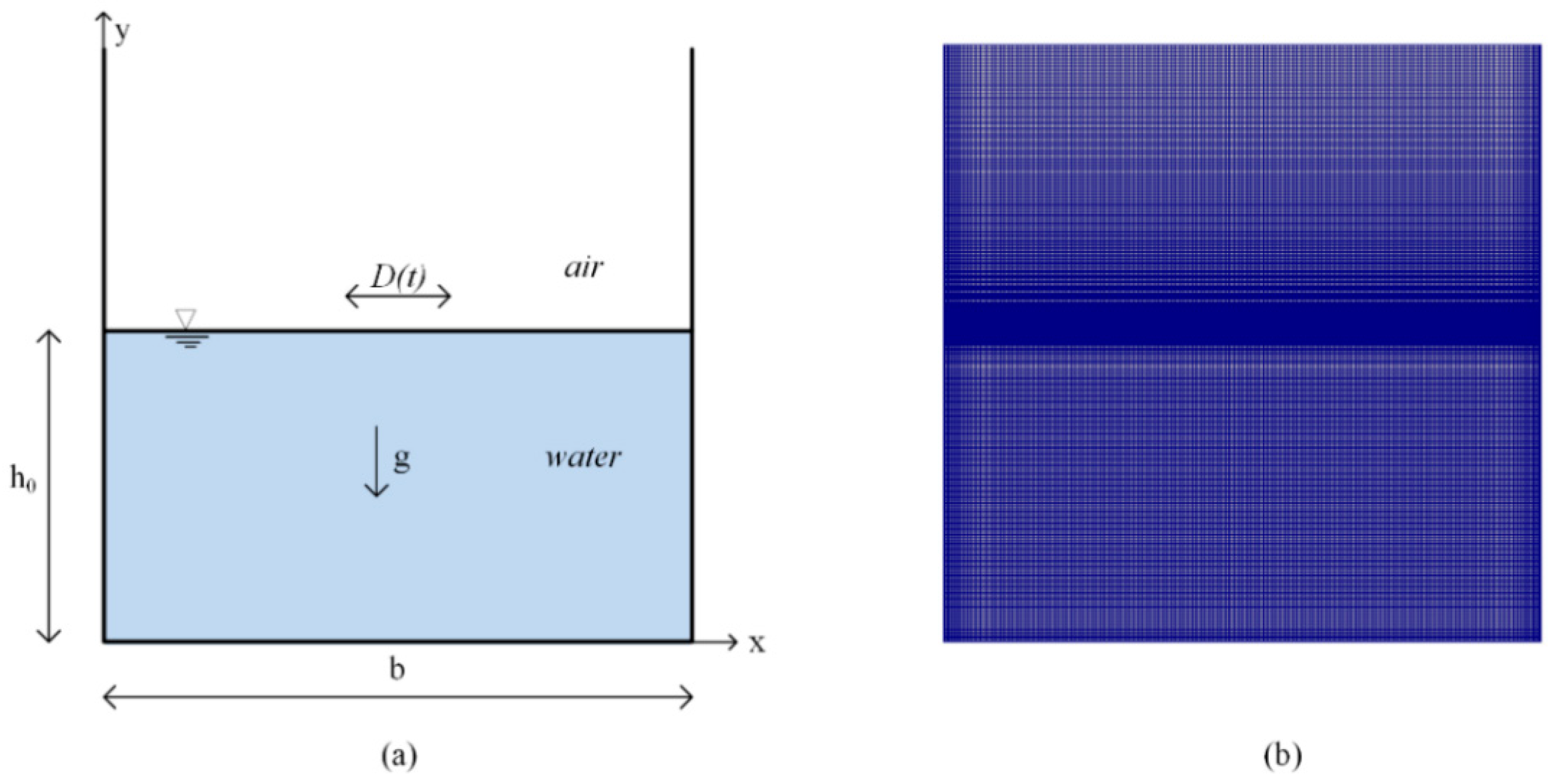
The proposed model and its solution are validated with the experimental measurements of Okamoto and Kawahara [32]. In their study, the authors recorded sloshing waves using a video camera during sinusoidal excitation of the tank, shown in Figure 1a. Acceleration was induced by a shaking table starting from the rest. The width of the tank is and the initial water depth in the tank is . The tank is subjected to the sinusoidal horizontal oscillation, , where is the amplitude of the displacement, which was selected as 0.93 cm, and is the angular frequency of the excitation, which was selected to be the same as the natural frequency of the tank, in order to observe large amplitude sloshing waves in the container. Therefore, the accuracy of the numerical model can be assessed for the resonance case, which is a severe test case for a free-surface solver.
Two-dimensional numerical simulations are performed for the validation case, as the experimental studies were conducted using a tank 10 cm in breadth, which is this slim in order to see the three-dimensional effects. A structured grid system is adopted refining the mesh size near the sidewalls and bottom, as well as near the free-surface, to capture sharp variations in the flow variables. A series of computational runs were performed on different grid resolutions, having different mesh numbers and mesh sizes within the refined regions. The computational mesh shown in Figure 1b consists of 45,000 computational cells. It should be noted that the dimensionless wall distance, , on the wall boundary is variable in time during unsteady simulation.
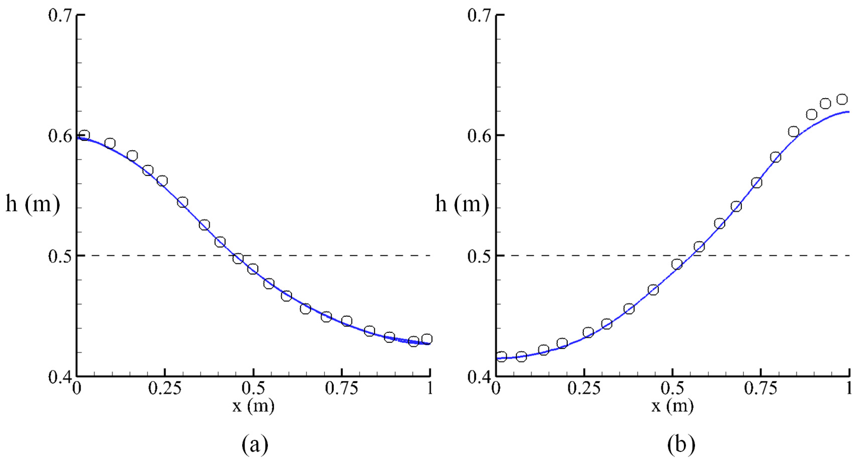
Based on the mesh independent numerical results, the position of the free-surface was extracted as an isosurface by means of the threshold value of F = 0.5, then, the free-surface profiles were plotted in Figure 2, in order to be compared with the existing experimental results at different times. The good agreement between the numerical and experimental results shows that the present numerical model can capture the spatial and temporal variations of the sloshing motion, even for the resonance case. The small discrepancy between the numerical and experimental results observed near the right wall at t = 3.55 s may be because of the contact angle on the transparent acrylic tank walls used in the experimental study of Okamoto and Kawahara [32].
The minimum, maximum, and average values of the on the walls of the tank are given in Table 1 for different instants of time. The time variation of the is significant at the bottom of the tank, but it is almost independent of time at the left and right walls, because the bottom is more sensitive to the temporal variations of shear stresses than that on the vertical walls. The resolution of the computational mesh near the walls is fine enough to capture the separation effects, which has a prominent effect on the internal baffles.
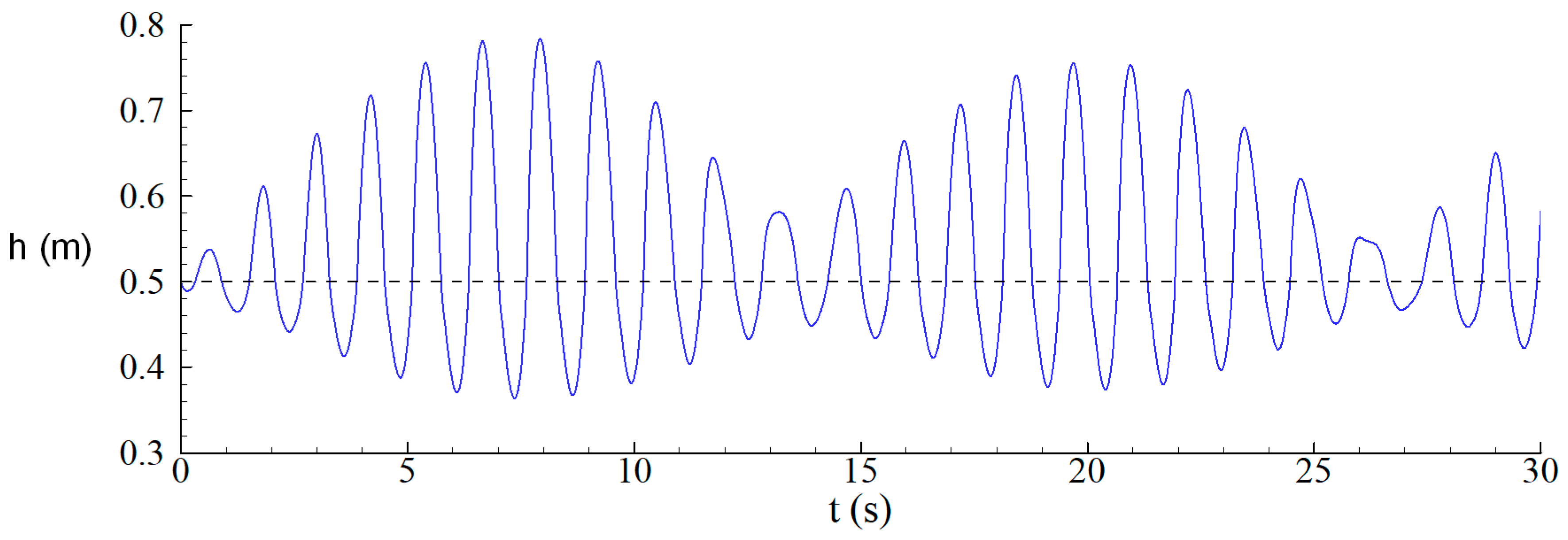
Figure 3 shows the time variation of the free-surface level at the left wall of the tank. The resonating surface wave on the wall can be clearly seen in the figure, even though the oscillation parameters remain constant during the simulation. Thus, the present numerical model is capable of simulating the resonating waves in the container.
3.2. Energy Dissipation in Sloshing Motion
The total energy of the liquid inside the tank is the sum of the potential and kinetic energy neglecting the surface-tension energy, as follows:
The kinetic and potential energy of the liquid within a computational cell is calculated at the center of the cell, and is integrated over the entire domain using the following expressions to obtain the total kinetic and potential energy of the liquid inside the tank:
where is the magnitude of the fluid velocity at the cell center, and y is the vertical distance from the tank bottom to the center of the cell. The use of an open source code allows us to calculate the above definitions by modifying the standard solver, interDymFoam. The integrated values are calculated during the simulation, and are written to an output file with the sampling frequency of 100 Hz. The F-value in the cell is included in the above definitions, so as to calculate the energy components in the cells occupied by the liquid during the simulation.
The maximum surface wave run-up or run-down on the sidewalls are generally evaluated in the literature to assess the performance of a damper. In this study, the time variation of the internal kinetic energy of the liquid within the tank is also evaluated, so as to see the damping of the sloshing effects, which is more precise than the common methods.
3.3. The Slot-Baffle Damper in the Tank
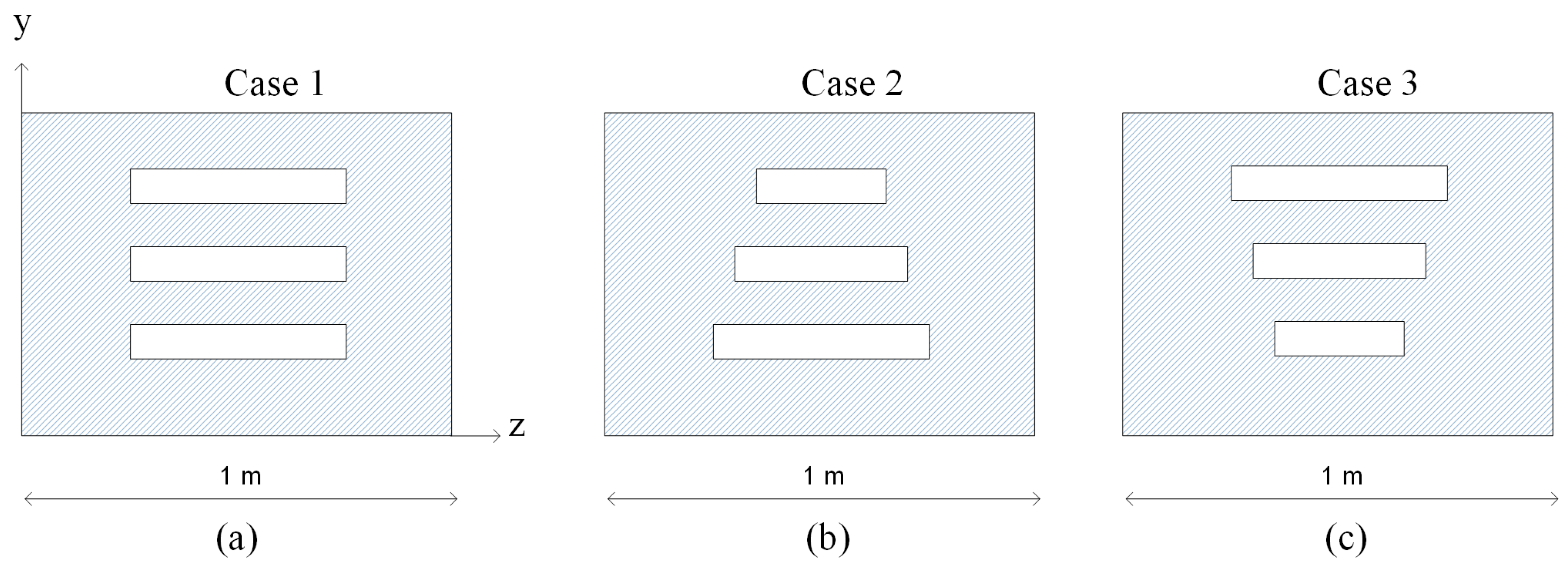
The slot-baffle has been successfully used by the authors in the mixing tank to enhance the mixing performance in water treatment [24]. This design creates new mixing zones using the self-momentum and energy of the fluid. The idea of creating an additional turbulence field in an accelerated container using the slot-baffle is investigated in this study. A slot-baffle is installed in the mid-section of the tank in the transverse direction. Various slot configurations are designed to compare the energy dissipation performance (Figure 4). The slot widths are equal to half of the width of the baffle (0.5 m) in Case 1. In Case 2, the slot widths reduce in y direction, by 0.5, 0.4, and 0.3 m. Case 3 is the symmetric version of the Case 2, in which the slot width increases in y direction. The slot heights are selected as 2 cm in each case, as shown in Figure 4. Three-dimensional numerical simulations are performed using the tank geometry (1 m in length, 1.2 m in height, and 1 m in breadth) without and with the slot-baffle.
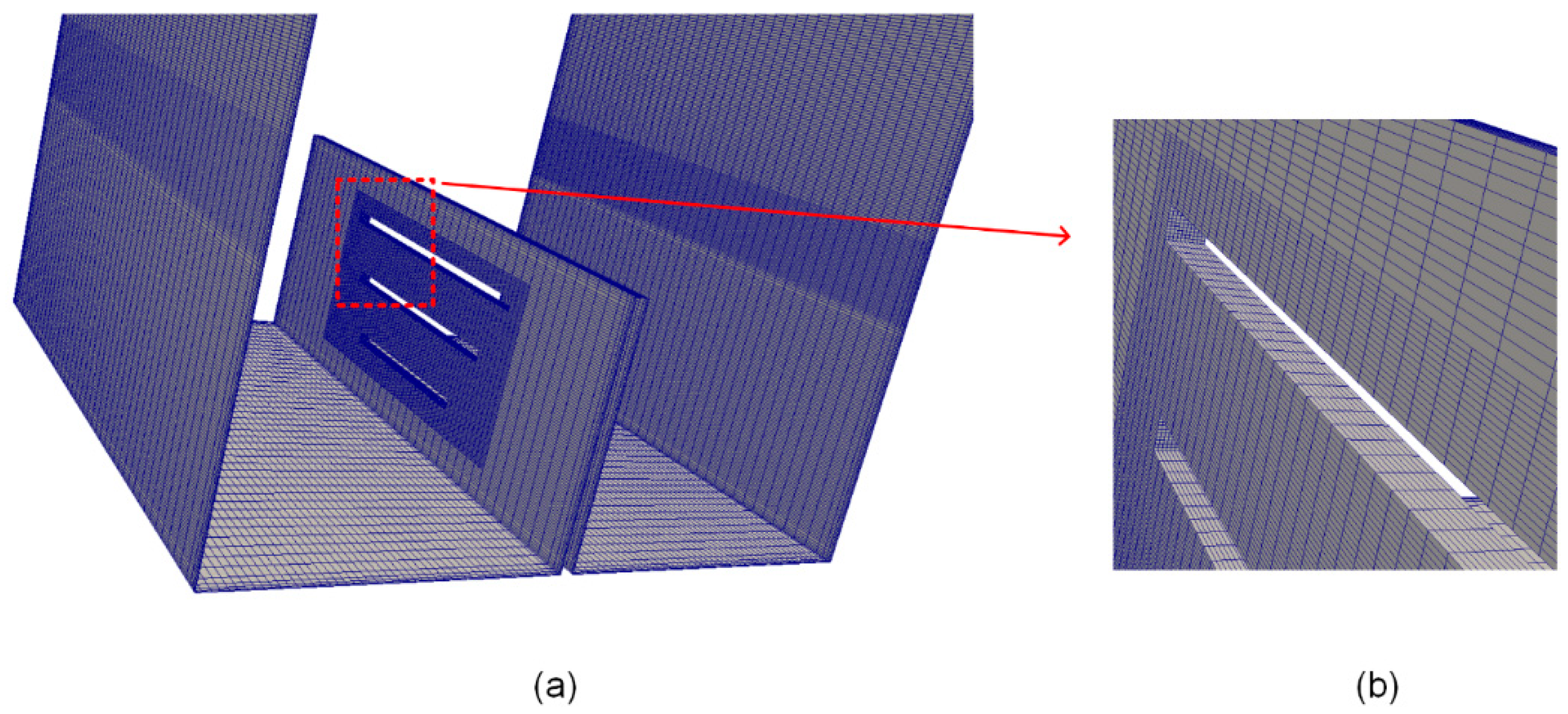
The three-dimensional view of the computational mesh of the tank walls is shown in Figure 5. A mesh manipulation procedure using two-step is adopted to create the slots on the baffle. In the first step, the original mesh is refined in a cubic region near the slots. This feature allows us to create slim slots on the baffle, containing cells with low skewness, and for us to capture high gradients near the baffles. Otherwise, computational cells with high skewness may cause the accuracy of the numerical solution in order to reduce in those regions. In the second step, the computational cells on the baffle, which coincide in the slots, are extruded in the x direction, so as to connect the two frontal faces of the baffle using the refined cells with the same topology. Using this procedure, the slots with arbitrary locations and dimensions can be created on the baffle.
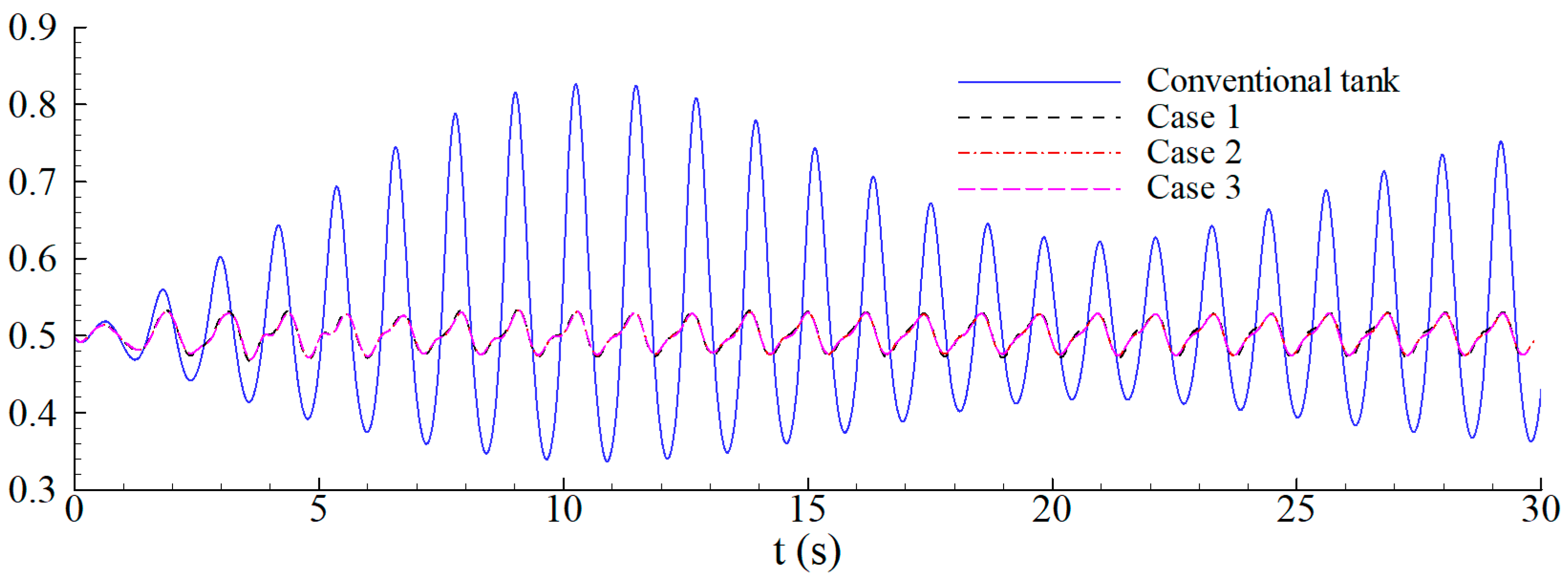
Numerical simulations were performed for each case during 30 oscillation periods, and time dependent variations of the water depth at the left wall are recorded and compared in Figure 6, so as to observe the dissipation performance of each baffle design. As can be seen, the slot-baffle design can significantly reduce the wave displacement and can remedy the resonance sloshing effects during oscillation. This comparison shows that this type of the slot configuration has a minor effect on suppressing the wave displacements during the oscillation period.
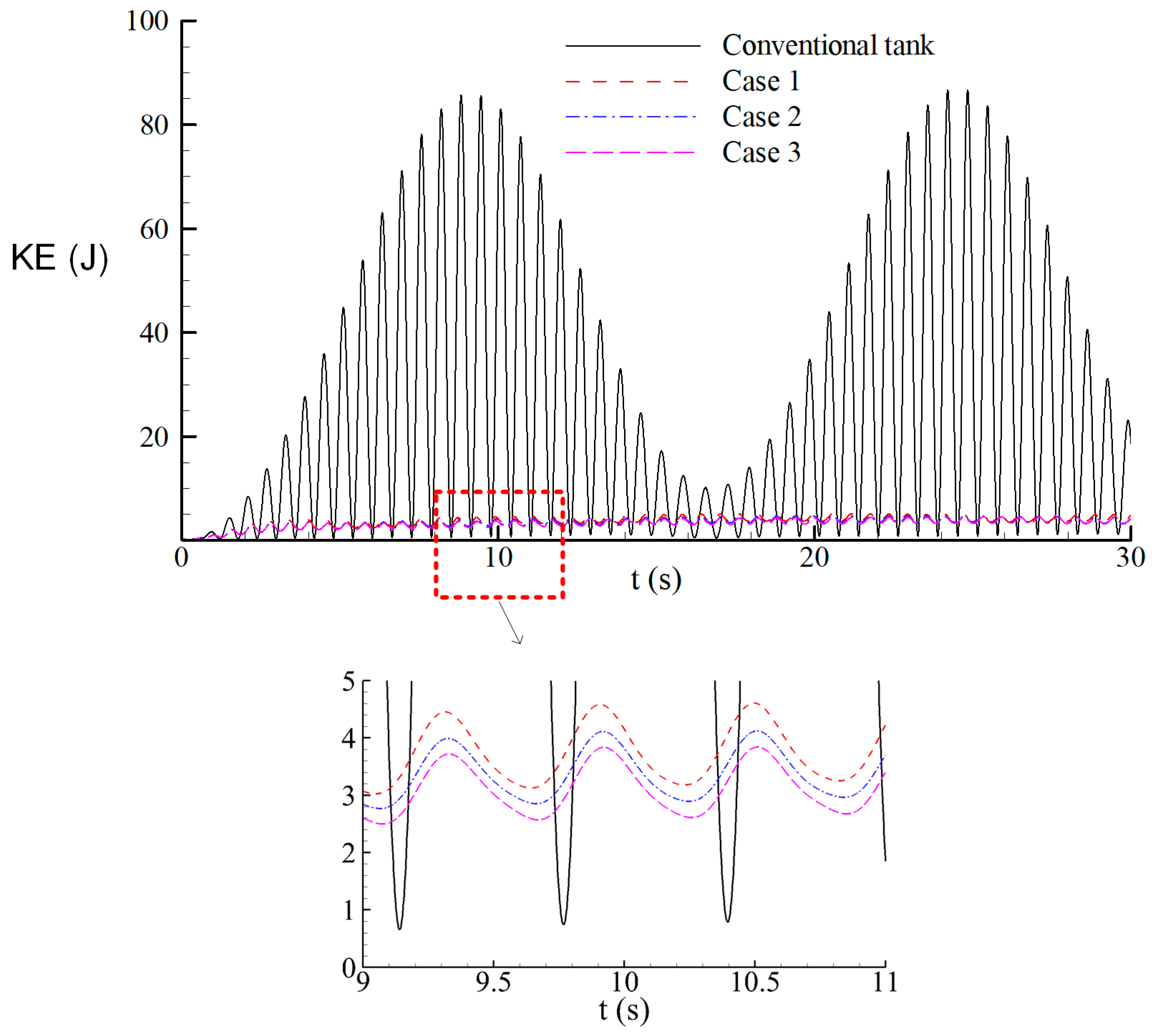
In order to evaluate the dissipation performance of each baffle type, the time variation of the internal kinetic is plotted in Figure 7, for each baffle type along with the conventional tank design. As seen in the zoomed view, Case 3 shows the best dissipation performance among the slot configurations considered. The present calculation of the internal kinetic energy of the liquid inside the tank enabled us to critically assess the dissipation performance of the slot-baffle design.
Figure 7 shows that the maximum wave run-up on the tank wall occurs at t = 9.5 s. The free-surface profiles are compared at this time level in Figure 8, with and without a slot-baffle in the tank. It is clearly seen that the resonating sloshing waves in the tank can successfully be damped by the slot-baffle, using the self-energy of the liquid inside the container.
The total energy dissipation rate (TEDR) of the slot-baffle design during the excitation period can be calculated from the following definition [33]:
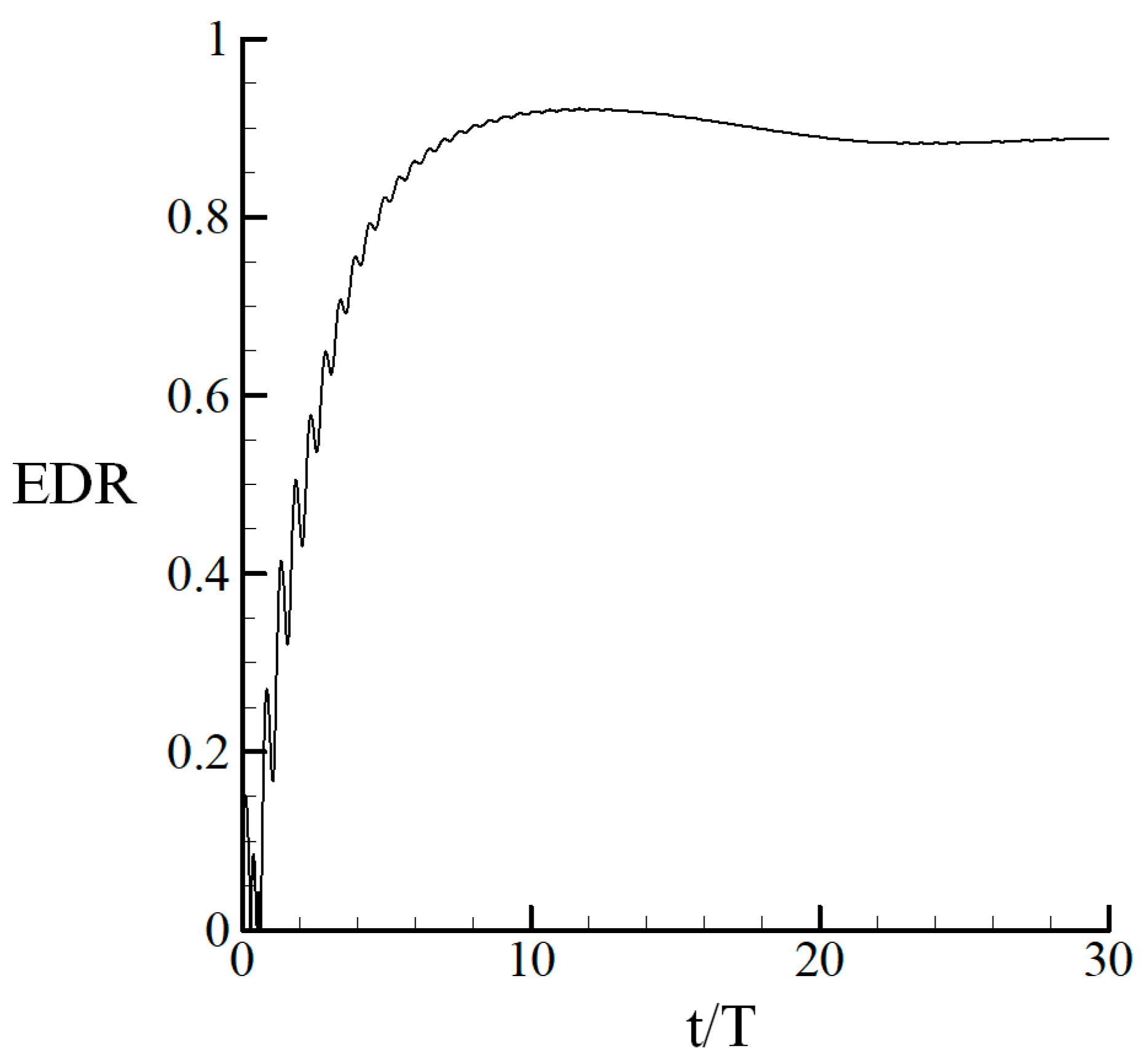
Here, and are the average total kinetic energy within the container for conventional and slot designs, respectively. The total dissipation rate of the Case 3 design is calculated as 88.12%, using the above definition. This suggests that the proposed slot-baffle design can dissipate the total kinetic energy by 88.12% over 30 oscillation periods. It is possible to assess the time variation of the dissipation rate by applying the moving-average approach to calculate the TEDR at time level t, as follows:
The average TKE at a time level t is calculated based on the data subset from 0 to t using Matlab. The time variation of the energy dissipation rate during oscillation is shown in Figure 9. The maximum dissipation ratio is observed at approximately the same time level as that which the maximum wave run-up occurs. This proves that the present design can effectively damp the sloshing effects depending on the internal kinetic energy of the fluid.
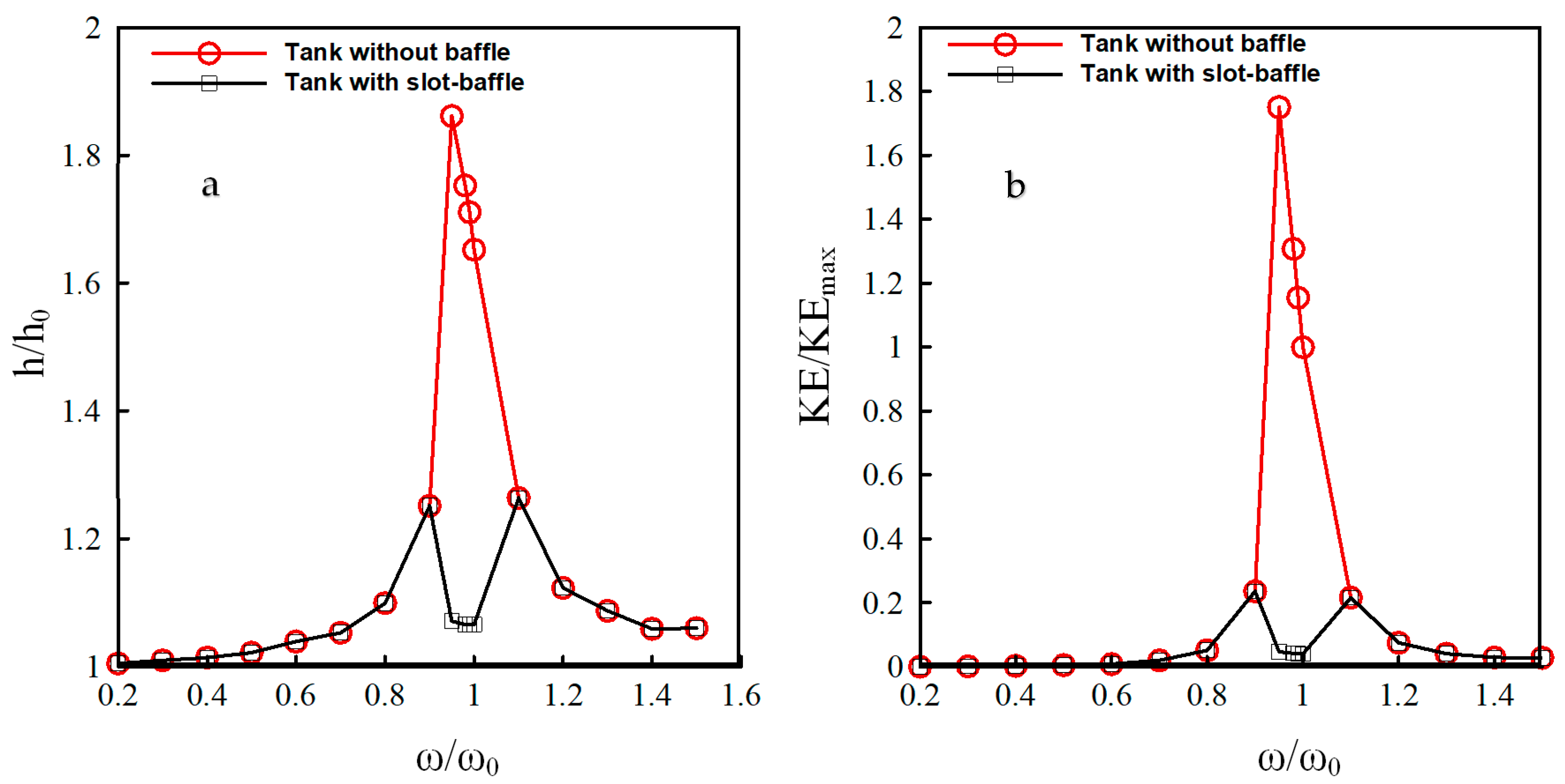
Three-dimensional numerical simulations are performed using different oscillation frequencies (ω/ω0 = 0.2, 0.3, 0.4, 0.5, 0.6, 0.7, 0.8, 0.9, 0.95, 0.98, 0.99, 1.0, 1.1, 1.2, 1.3, 1.4, and 1.5) in order to see the energy dissipation performance of the present design (Case 3). The simulation duration is set to 30 oscillation periods for each simulation, in order to see the possible severe sloshing effects. The computational mesh in the three-dimensional geometry consists of approximately 1.25 million cells. The three-dimensional numerical simulations for the conventional and the novel designs took about one month, using 28 computational nodes for each case on a TRUBA high performance computing center. The maximum wave run-up on the left wall during the simulation is determined for each simulation, and is plotted in Figure 10a, with variation of oscillation frequency for conventional and proposed tank designs. The water depth and oscillation frequency are non-dimensionalized with respect to the initial water depth in the tank and the natural frequency of the partially filled tank. The maximum water height at the left wall was observed for ω/ω0 = 0.95, as the natural frequency, ω0, was determined by neglecting the three-dimensional and viscous effects (. This proves that the analytical formula over predicts the natural frequency of the partially-filled rectangular tank, as the viscous and three-dimensional effects introduce additional damping into the oscillating system. As observed in Figure 10a, the slot-baffle can dissipate the sloshing effects near the resonance case more than those observed for other cases, as the present design uses the self-energy of the liquid. The same behavior is observed in the variation of the internal kinetic energy with the oscillation frequency in Figure 10b. When the internal energy of the liquid becomes high, the dissipation rate using the present design is also high. The reflected fluid segments from the walls of the tank are allowed to pass from the slots, and this causes the collision of the emerging fluid particles with the accelerating fluid parcels in the subsequently created chamber. This inverse effect of the present design shows an effective dissipation performance for moving containers. It is possible to use more than one baffle inside the tank, depending on the length of the container.
4. Conclusions
Non-linear liquid sloshing in an accelerated tank is investigated based on the three-dimensional numerical simulations using OpenFOAM. The previously developed slot-baffle design for the enhancement of the mixing of water treatment contact tanks is successfully used inside the container for the dissipation of the resonating sloshing waves. The wave run-up on the tank wall and the internal kinetic energy of the liquid are monitored during acceleration, and are used for the assessment of the dissipation performance of the proposed design. The present design could dissipate the 88.12% of the internal kinetic energy of the liquid over 30 periods of oscillations for the resonance case. Three-dimensional numerical simulations for different oscillation frequencies reveal that the present design can successfully dampen the sloshing effects over a wide range of period of oscillation. The slot-baffle design shows the best dissipation performance for the resonance case, as the present design uses the self-energy of the liquid for the dissipation. This inverse effect of the proposed design can lead to damp oscillation effects during acceleration of liquid containers.
Supplementary Materials
The following are available online at https://www.mdpi.com/2073-4441/10/11/1565/s1, Video S1: Comparison of sloshing motions in tank without baffle and tank with slot-baffle.
Author Contributions
Conceptualization, E.D. and M.M.A.; Methodology, E.D.; Software, E.D.; Validation, E.D.; Formal Analysis, E.D. and M.M.A.; Investigation, E.D. and M.M.A.; Resources, E.D.; Data Curation, E.D. and M.M.A.; Writing-Original Draft Preparation, E.D. and M.M.A.; Writing-Review & Editing, E.D. and M.M.A.; Visualization, E.D.; Supervision, M.M.A.
Funding
This research received no external funding.
Acknowledgments
The numerical calculations reported in this paper were fully performed at TUBITAK ULAKBIM, the High Performance and Grid Computing Center (TRUBA resources).
Conflicts of Interest
The authors declare no conflicts of interest.
References
- Xue, M.-A.; Zheng, J.H.; Lin, P.; Yuan, X. Experimental study on vertical baffles of different configurations in suppressing sloshing pressure. Ocean Eng. 2017, 136, 178–189. [Google Scholar] [CrossRef]
- Xue, M.-A.; Lin, P. Numerical study of ring baffle effects on reducing violent liquid sloshing. Comput. Fluids 2011, 52, 116–129. [Google Scholar] [CrossRef]
- Xue, M.-A.; Lin, P.; Zheng, J.H.; Ma, Y.; Yuan, X.; Nguyen, V.T. Effects of perforated baffle on reducing sloshing in rectangular tank: Experimental and numerical study. China Ocean Eng. 2013, 27, 615–628. [Google Scholar] [CrossRef]
- Nakayamaf, T.; Washizus, K. The Boundary Element Method Applied to Nonlinear Sloshing Problems the Analysis of Two-Dimensional. Int. J. Numer. Methods Eng. 1981, 17, 1631–1646. [Google Scholar] [CrossRef]
- Cho, J.R.; Lee, H.W.; Ha, S.Y. Finite element analysis of resonant sloshing response in 2-D baffled tank. J. Sound Vib. 2005, 288, 829–845. [Google Scholar] [CrossRef]
- Wu, C.H.; Faltinsen, O.M.; Chen, B.F. Dynamics of vortex evolution in a 2D baffled tank. Comput. Math. Appl. 2016, 71, 1–28. [Google Scholar] [CrossRef] [Green Version]
- Lu, L.; Jiang, S.C.; Zhao, M.; Tang, G.Q. Two-dimensional viscous numerical simulation of liquid sloshing in rectangular tank with/without baffles and comparison with potential flow solutions. Ocean Eng. 2015, 108, 662–677. [Google Scholar] [CrossRef]
- El-Kamali, M.; Schotté, J.S.; Ohayon, R. Three-dimensional modal analysis of sloshing under surface tension. Int. J. Numer. Methods Fluids 2011, 65, 87–105. [Google Scholar] [CrossRef]
- Veldman, A.E.P.; Gerrits, J.; Luppes, R.; Helder, J.A.; Vreeburg, J.P.B. The numerical simulation of liquid sloshing on board spacecraft. J. Comput. Phys. 2007, 224, 82–99. [Google Scholar] [CrossRef]
- Chen, Y.G.; Price, W.G. Numerical simulation of liquid sloshing in a partially filled container with inclusion of compressibility effects. Phys. Fluids 1999, 21, 1–16. [Google Scholar] [CrossRef]
- Godderidge, B.; Turnock, S.; Earl, C.; Tan, M. The effect of fluid compressibility on the simulation of sloshing impacts. Ocean Eng. 2009, 36, 578–587. [Google Scholar] [CrossRef]
- Liu, D.; Lin, P. Three-dimensional liquid sloshing in a tank with baffles. Ocean Eng. 2009, 36, 202–212. [Google Scholar] [CrossRef]
- Maleki, A.; Ziyaeifar, M. Sloshing damping in cylindrical liquid storage tanks with baffles. J. Sound Vib. 2008, 311, 372–385. [Google Scholar] [CrossRef]
- Akyildiz, H. A numerical study of the effects of the vertical baffle on liquid sloshing in two-dimensional rectangular tank. J. Sound Vib. 2012, 331, 41–52. [Google Scholar] [CrossRef]
- Cho, I.H.; Choi, J.S.; Kim, M.H. Sloshing reduction in a swaying rectangular tank by an horizontal porous baffle. Ocean Eng. 2017, 138, 23–34. [Google Scholar] [CrossRef]
- Wei, Z.J.; Faltinsen, O.M.; Lugni, C.; Yue, Q.J. Sloshing-induced slamming in screen-equipped rectangular tanks in shallow-water conditions. Phys. Fluids 2015, 27, 032104. [Google Scholar] [CrossRef]
- Marivani, M.; Hamed, M.S. Numerical Study of Slat Screen Pattern Effect on Design Parameters of Tuned Liquid Dampers. J. Fluids Eng. 2014, 136, 061201. [Google Scholar] [CrossRef]
- Molin, B.; Remy, F. Inertia effects in TLD sloshing with perforated screens. J. Fluids Struct. 2015, 59, 165–177. [Google Scholar] [CrossRef]
- Maravani, M.; Hamed, M.S. Numerical modeling of sloshing motion in a tuned liquid damper outfitted with a submerged slat screen. Int. J. Numer. Methods Fluids 2011, 65, 834–855. [Google Scholar] [CrossRef]
- Tait, M.J.; El Damatty, A.A.; Isyumov, N. An investigation of tuned liquid dampers equipped with damping screens under 2D excitation. Earthq. Eng. Struct. Dyn. 2005, 34, 719–735. [Google Scholar] [CrossRef]
- Demirel, E.; Aral, M.M. Unified analysis of multi-chamber contact tanks and mixing efficiency evaluation based on vorticity field. Part I: Hydrodynamic analysis. Water 2016, 8, 495. [Google Scholar] [CrossRef]
- Demirel, E.; Aral, M.M. Unified analysis of multi-chamber contact tanks and mixing efficiency evaluation based on vorticity field. Part II: Transport analysis. Water 2016, 8, 537. [Google Scholar] [CrossRef]
- Demirel, E.; Aral, M.M. An evaluation of performance of efficiency indexes for contact tanks. J. Environ. Eng. 2018, 144. [Google Scholar] [CrossRef]
- Demirel, E.; Aral, M.M. An efficient contact tank design for potable water treatment. Tech. J. 2018, 29, 8279–8294. [Google Scholar] [CrossRef]
- OpenFOAM. The OpenFOAM Foundation; OpenCFD Ltd.: Bracknell, UK, 2015. [Google Scholar]
- Menter, F.R. Zonal Two Equation k-omega, Turbulence Models for Aerodynamic Flows. AIAA Pap. 1993, 21. [Google Scholar] [CrossRef]
- Hirt, C.W.; Nichols, B.D. Volume of fluid (VOF) method for the dynamics of free boundaries. J. Comput. Phys. 1981, 39, 201–225. [Google Scholar] [CrossRef]
- Weller, H.G.; Tabor, G.; Jasak, H.; Fureby, C. A tensorial approach to computational continuum mechanics using object-oriented techniques. Comput. Phys. 1998, 12, 620–631. [Google Scholar] [CrossRef]
- Malecha, Z.M.; Jedrusyna, A.; Grabowski, M.; Chorowski, M.; van Weelderen, R. Experimental and numerical investigation of the emergency helium release into the LHC tunnel. Cryogenics 2016, 80. [Google Scholar] [CrossRef]
- Lubryka, E.; Malecha, Z.M. The numerical boundary conditions of the wrapping pattern of thin insulation. Int. J. Heat Mass Transf. 2017, 108. [Google Scholar] [CrossRef]
- Demirel, E.; Aydin, I. Global volume conservation in unsteady free surface flows with energy absorbing far-end boundaries. Int. J. Numer. Methods Fluids 2010, 64, 689–708. [Google Scholar] [CrossRef]
- Okamoto, T.; Kawahara, M. Two-dimensional sloshing analysis by Lagrangian finite element method. Int. J. Numer. Methods Fluids 1990, 11, 453–477. [Google Scholar] [CrossRef]
- Iranmanesh, A.; Passandideh-Fard, M. A 2D numerical study on suppressing liquid sloshing using a submerged cylinder. Ocean Eng. 2017, 138, 55–72. [Google Scholar] [CrossRef]
Figure 1.
Sinusoidal oscillation of a rectangular tank with resonance frequency: (a) schematic view of the geometry of the oscillating tank and (b) two-dimensional mesh used in the numerical solution.
Figure 1.
Sinusoidal oscillation of a rectangular tank with resonance frequency: (a) schematic view of the geometry of the oscillating tank and (b) two-dimensional mesh used in the numerical solution.

Figure 2.
Comparison of the calculated free-surface profile with the experimental measurements at different time values: (a) t = 2.95 s and (b) t = 3.55 s. Continuous lines represent the present numerical results, circles represent the measurements of Okamoto and Kawahara (1990), and the dashed line represents the initial water level in the tank.

Figure 3.
Time variation of the water depth at the left wall during the sinusoidal oscillation of the tank. The dashed line represents the initial water level in the tank.
Figure 3.
Time variation of the water depth at the left wall during the sinusoidal oscillation of the tank. The dashed line represents the initial water level in the tank.

Figure 4.
Various slot configurations on the solid baffle: (a) Slot widths are equal; (b) Slot width is decreasing in y direction and (c) Slot width is increasing in y direction.
Figure 4.
Various slot configurations on the solid baffle: (a) Slot widths are equal; (b) Slot width is decreasing in y direction and (c) Slot width is increasing in y direction.

Figure 5.
Three-dimensional view of the computational mesh on the walls: (a) mesh refinement near the slots and (b) close-up view of the refined region near the slots.
Figure 5.
Three-dimensional view of the computational mesh on the walls: (a) mesh refinement near the slots and (b) close-up view of the refined region near the slots.

Figure 6.
Comparison of the wave run-up on the left wall for various slot configurations.

Figure 7.
Comparison of the internal kinetic energy of the liquid inside the tank for different slot configurations.
Figure 7.
Comparison of the internal kinetic energy of the liquid inside the tank for different slot configurations.

Figure 8.
Comparison of three-dimensional views of free-surface at t = 9.5 s. (a) Conventional tank and (b) slot-baffle design (a supplementary video file is available for the animation of the liquid sloshing).
Figure 8.
Comparison of three-dimensional views of free-surface at t = 9.5 s. (a) Conventional tank and (b) slot-baffle design (a supplementary video file is available for the animation of the liquid sloshing).

Figure 9.
Time variation of the energy dissipation rate during oscillation.

Figure 10.
Variation of (a) the maximum water depth at the tank wall and (b) internal kinetic energy of the liquid with oscillation frequency. Here, ω0 is the natural frequency of the partially filled rectangular tank.
Figure 10.
Variation of (a) the maximum water depth at the tank wall and (b) internal kinetic energy of the liquid with oscillation frequency. Here, ω0 is the natural frequency of the partially filled rectangular tank.


Table 1.
Dimensionless wall distance at different instants of time.
| Wall | ||||||
|---|---|---|---|---|---|---|
| T = 2.95 s | T = 3.55 s | T = 2.95 s | T = 3.55 s | T = 2.95 s | T = 3.55 s | |
| Left | 0.19 | 0.16 | 25.53 | 25.65 | 7.95 | 3.64 |
| Right | 0.14 | 0.19 | 24.72 | 25.61 | 3.73 | 8.94 |
| Bottom | 2.09 | 2.12 | 7.44 | 9.15 | 5.25 | 6.22 |
© 2018 by the authors. Licensee MDPI, Basel, Switzerland. This article is an open access article distributed under the terms and conditions of the Creative Commons Attribution (CC BY) license (http://creativecommons.org/licenses/by/4.0/).
Share and Cite
MDPI and ACS Style
Demirel, E.; Aral, M.M. Liquid Sloshing Damping in an Accelerated Tank Using a Novel Slot-Baffle Design. Water 2018, 10, 1565. https://doi.org/10.3390/w10111565
AMA Style
Demirel E, Aral MM. Liquid Sloshing Damping in an Accelerated Tank Using a Novel Slot-Baffle Design. Water. 2018; 10(11):1565. https://doi.org/10.3390/w10111565
Chicago/Turabian StyleDemirel, Ender, and Mustafa M. Aral. 2018. "Liquid Sloshing Damping in an Accelerated Tank Using a Novel Slot-Baffle Design" Water 10, no. 11: 1565. https://doi.org/10.3390/w10111565
Note that from the first issue of 2016, this journal uses article numbers instead of page numbers. See further details here.