Study of Hydrodynamic Interference of Vertical-Axis Tidal Turbine Array


1
Faculty of Maritime and Transportation, Ningbo University, Ningbo 315611, China
2
Wuhan Rules and Research Institute, China Classification Society, Wuhan 430022, China
3
School of Naval Architecture and Mechanical-electrical Engineering, Zhejiang Ocean University, Zhoushan 316022, China
*
Authors to whom correspondence should be addressed.
Water 2018, 10(9), 1228; https://doi.org/10.3390/w10091228
Submission received: 12 August 2018
/
Revised: 3 September 2018
/
Accepted: 4 September 2018
/
Published: 12 September 2018
(This article belongs to the Section Hydraulics and Hydrodynamics)
Abstract
:The hydrodynamic interference between tidal turbines must be considered when predicting their overall hydrodynamic performance and optimizing the layout of the turbine array. These factors are of great significance to the development and application of tidal energy. In this paper, the phenomenon of hydrodynamic interference of the tidal turbine array is studied by the hydrodynamic performance forecast program based on an unsteady boundary element model for the vertical-axis turbine array. By changing the relative positions of two turbines in the double turbine array to simulate the arrangement of different turbines, the hydrodynamic interference law between the turbines in the array and the influence of relative positions on the hydrodynamic characteristics in the turbine array are explored. The manner in which the turbines impact each other, the degree of influence, and rules for turbine array arrangement for maximum efficiency of the array will be discussed. The results of this study will provide technical insights to relevant researchers.
1. Introduction
Due to an increasingly severe energy crisis, environmental damage, and other issues, China must focus on its energy infrastructure by developing renewable energy sources. Therefore, promoting the development and utilization of China’s clean and renewable energy resources in the future will be an important strategy [1,2]. Tidal current energy is one viable option and compared with other renewable energy approaches, it is more concentrated. The energy density is about thirty times that of solar energy and four times that of wind energy [3]. The energy flux density of tidal current energy is huge and this means that the geometric scale of the transducer is relatively small, the scale of the project is controlled, and the influence on the ecological environment is relatively small. Because tidal energy has the advantages above, many countries are competing to develop technology to harness tidal current energy. An efficient transducer requires a simple structure, easy maintenance, and small impact on the ecological environment and human activities. The design and large-scale engineering of efficient transducers have become the focus of tidal current energy research at home and abroad.
Hydraulic turbines, which are wheel-type ocean tidal current transducers, are widely used in current energy applications. According to the relationship between the main shaft of the hydraulic turbine and the direction of the flow, it can be divided into a horizontal axis turbine and vertical axis turbine. The hydraulic turbine whose main shaft is parallel to the direction of the flow is called the horizontal axis turbine, and the hydraulic turbine whose main shaft is perpendicular to the direction of the flow is called the vertical axis hydraulic turbine. For example, some of the horizontal axis turbines are the British AK-1000TM [4], SeaGen [5], Tidel [6], and Irish Open Centre [7]. While Canada’s Davis Hydro Turbine [8], EnCurrent [9], America’s Gorlov [10], OCGen [11], Italian Kobold [12], Wanxiang No. 1, Wanxiang No. 2, and Haineng No. 1 [3] are vertical axis turbines. The vertical axis turbine has the characteristic of not being subjected to flow direction restrictions and has a simple blade structure, low working tip-speed ratio, and low noise. The power generation system can be installed on the water surface, which is an attractive feature for researchers.
Like wind power generation, the centralized layout of the large-scale hydraulic turbine can better reflect its engineering application value. The arrangement of the hydraulic turbine is very important, and the arrangement of the high-volume hydro-generators affects the power output of the power station directly. Considering the hydrodynamic interaction between turbines in an array, it is of great practical significance to accurately predict the overall hydrodynamic performance of the hydraulic turbine array and further optimize the arrangement of the array. This can scale-up the tidal current power station and industrialize it. The arrangement of hydraulic turbines is generally in one of the following three ways: (1) the hydraulic turbines are only installed in a row, and the single row of hydraulic turbines is perpendicular to the direction of the ocean tidal current; (2) the hydraulic turbine array consists of two rows, and these two rows of hydraulic turbine are perpendicular to the direction of the ocean tidal current, and the two hydraulic turbines are staggered along the ocean flow; and (3) the turbine array which is perpendicular to the ocean’s current direction consists of three or more rows of turbines [13].
Many researchers at home and abroad have launched a preliminary study on the arrangement of turbines. Bai et al. [14] used the computational fluid dynamics (CFD) method to study the hydrodynamic performance of a horizontal axis turbine. Churchfield et al. [15] used large-eddy simulation (LES) to study the power and wake of the horizontal axis turbine. Turnuck et al. [16] used the blade element momentum theory (BEMT) and Reynolds-averaged Navier-Stokes (RANS) models to analyse the wake characteristics and overall efficiency of the horizontal axis turbine. Antheaume et al. [17] contrasted the efficiency of the vertical axis turbine and turbine array. Li et al. [18] studied the array of turbines containing two vertical axis turbines. Results showed that the spacing of the turbine along the flow direction was the main factor that impacted the output power of the turbine. Goude et al. [19] studied the efficiency of the fleet containing five vertical axis turbines, and analysed the advantages and disadvantages of “-” type and “Z” type turbine arrangement. Gebreslassie et al. [20] investigated the influence of wake interaction and blockage on the performance of individual turbines in a staggered configuration in a tidal stream farm using the CFD-based Immersed Body Force turbine modelling method. Zanforlin et al. [21] investigated the hydrodynamic interactions between three closely-spaced vertical axis tidal turbines using CFD. Giorgetti et al. [22] used the CFD to study the interference between medium-solidity Darrieus vertical axis turbines and analysed the physical mechanism of power enhancement of the turbines. Fengshan [13] used numerical simulation techniques to study the vertical axis tidal turbine array arrangement problem.
At present, there is no unified conclusion on the arrangement of turbines in tidal power plants, and there are some differences in the conclusions reached in different studies. Due to the complexity of the interaction problem between turbines, the previous studies were limited to a single parameter, such as the impact range of the turbine wake or the influence of the turbine transverse spacing on the energy conversion efficiency. Because of the above two points, the study of the tidal energy station turbine array arrangement is very urgent and important.
Based on boundary element theory, this paper developed a simplified algorithm that can quickly predict the relative power coefficient of a vertical axis turbine array. The hydrodynamic characteristic prediction program for a vertical axis turbine array was developed by adopting the method. The influence of the relative position of the turbines on the hydrodynamic characteristics in the turbine array operation and the hydrodynamic disturbances between the turbines in the turbine array were studied.
2. Methods
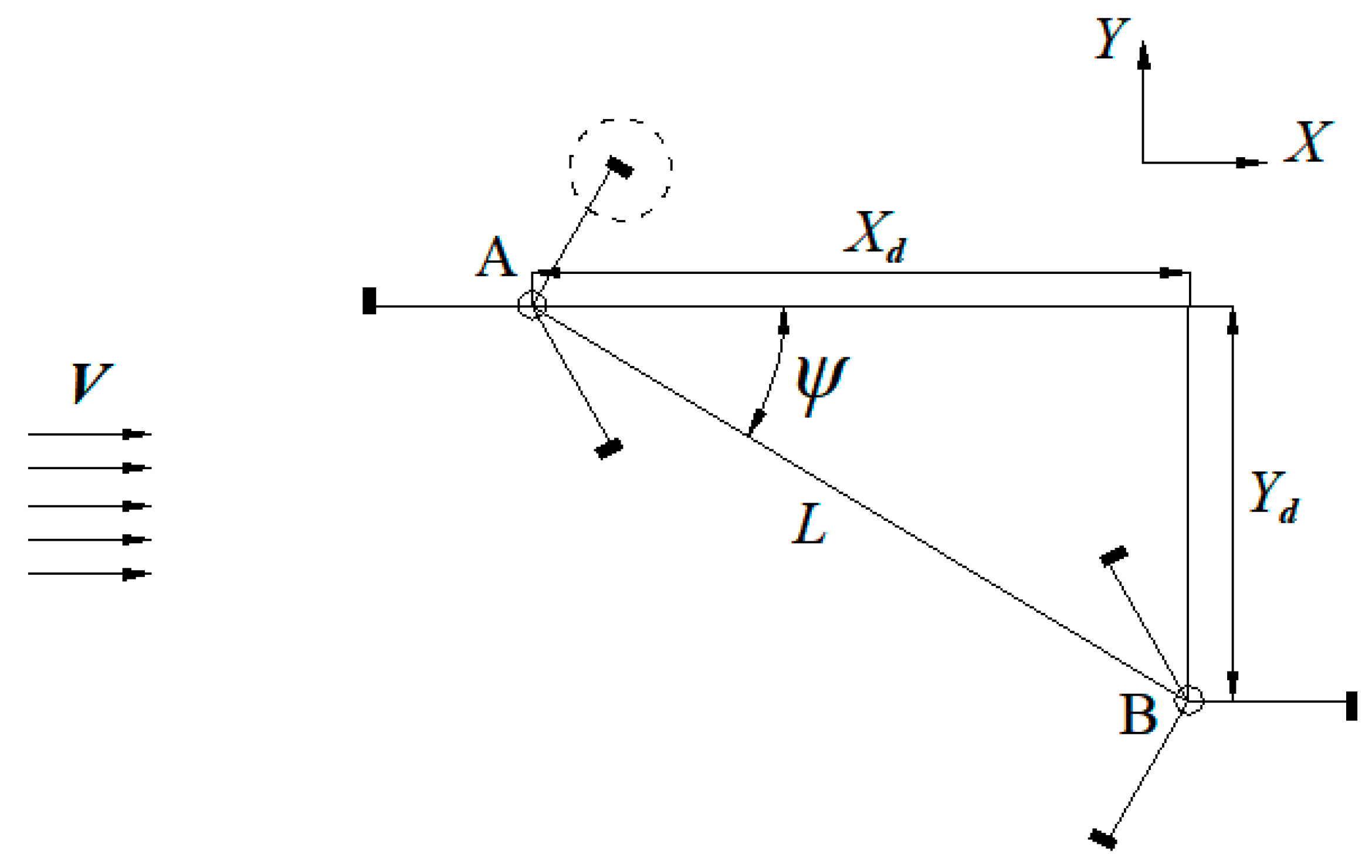
In this paper, the overall hydrodynamic characteristics of a vertical axis turbine array were studied by analysing the influence of changing the relative position of the two turbines. Figure 1 shows a turbine array containing two separate vertical axis turbines. The coordinates for the rotation centre for turbine A were defined as (x1, y1) and as (x2, y2) for turbine B. The relevant parameters in Figure 1 are expressed as
where is the deflection angle, L is the turbine spacing, and d is the distance between (x1, y1) and (x2, y2).
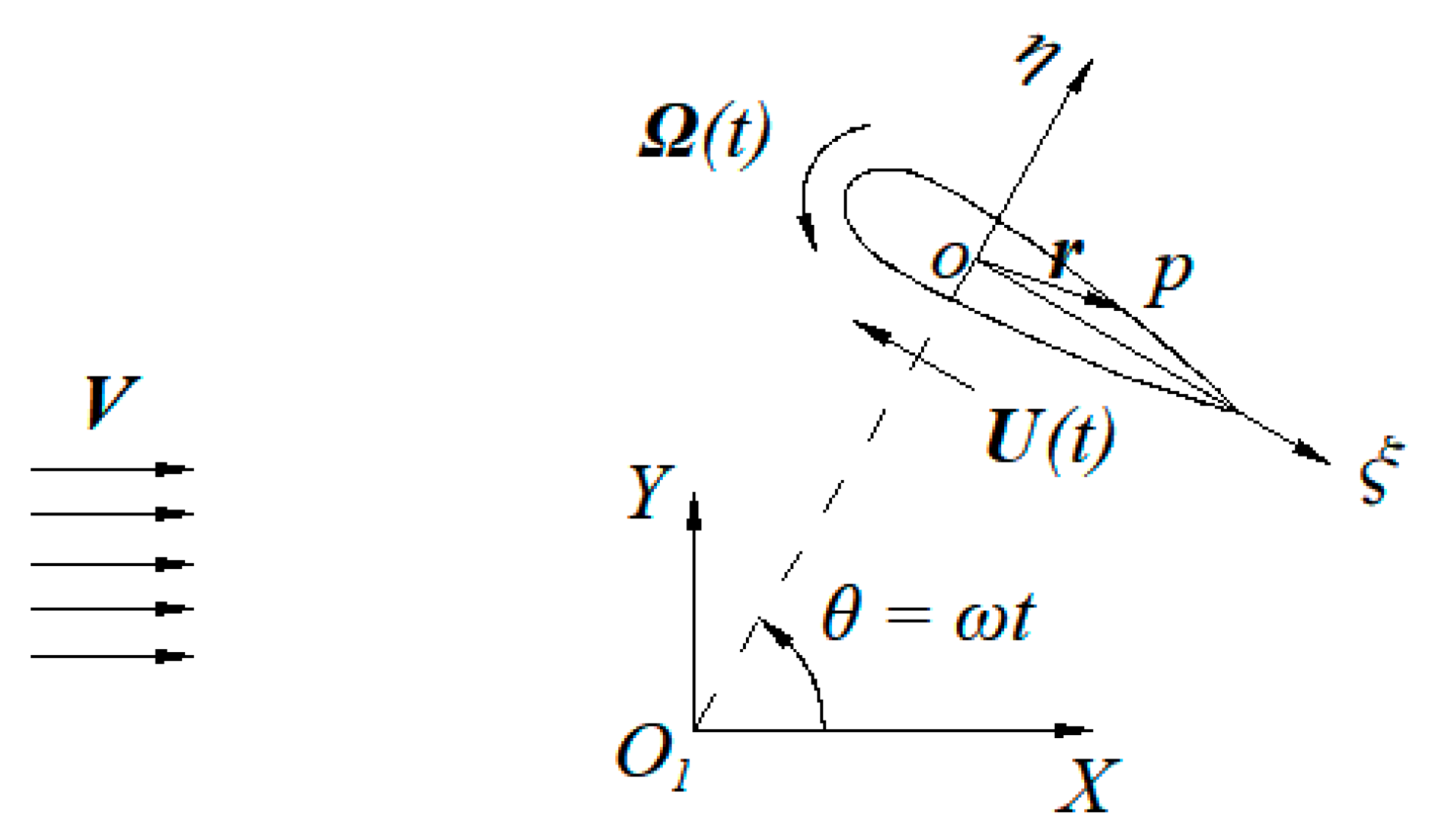
A close-up of the blade motion in the dotted circle in Figure 1 is shown in Figure 2, in which a moving coordinate system, , was fixed on each blade. The motion of the blade at a time, t, can be represented by two components, the rotating angular velocity, Ω(t), about the origin, o, and the translational velocity, U, of the origin, o. The azimuthal angle θ is defined as the angle that the blade rotates relative to the rotation center O1 of the turbine in time t, θ = ωt, in which ω is the angular velocity about the rotation center O1.
The velocity, , of a uniform incoming flow at infinity is
where is assumed to be the velocity potential at point, p, in the fluid domain, , and time t, which meets the Laplace equation:
The non-penetration boundary condition on the blade surface is
where nb is the normal of the blade surface, Sb; r is the vector from the origin, o, to any surface point in the coordinate system, . At infinity, satisfies the velocity potential for uniform incoming flow according to
If is the perturbation velocity potential, then can be decomposed into two parts:
Assuming a zero initial perturbation, should satisfy the following equation and boundary conditions:
where t0 is the initial time.
The blade force is expressed as
where S represents the blade surface and p is the pressure on the blade surface. The moment of the blade to reference point, o, is
The torque coefficient of a single blade in a turbine rotor is formulated as
where D is the diameter of turbine, b length of blade and R is the radius of the turbine. The force of each blade on a single turbine is superimposed to obtain the force of the whole rotor. If the force of the turbine is F and the torque is Q, then
where Z is the blade number of a single turbine. The resultant force coefficient of the turbine rotor is formulated as
And the average moment coefficient of the turbine rotor shaft is formulated as
The power coefficient can be defined as
The power coefficient of turbine A is defined as Cp1, the power coefficient of turbine B as Cp2 and the power coefficient of a single turbine under the same conditions as Cp. The relative power coefficient of double turbines array is
When Ψ = 90°, the turbine array is in parallel and the connecting line between the rotating axis of the turbines is perpendicular to the direction of tidal current. When Ψ = 0°, the turbine array is in series and the connecting line is parallel to the tidal current. A variety of different turbine arrangements can be simulated by changing L and Ψ. At the same time, the influence of the turbine steering on the turbine array is simulated by changing the relative rotation direction of the turbine.
3. Results
3.1. Issues of Turbine Array
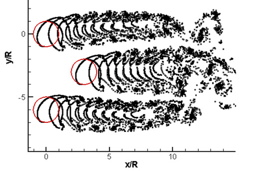
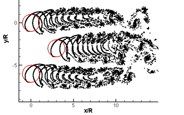
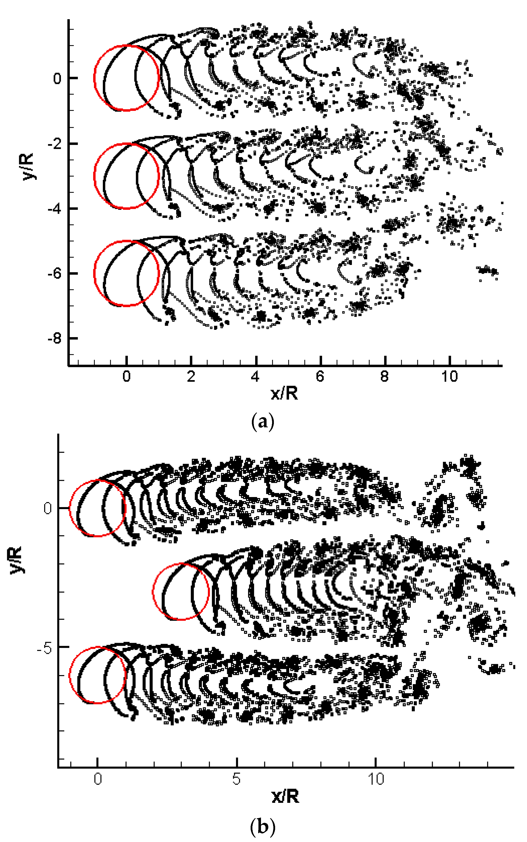
Figure 3a,b show the central path of trailing vortices in the turbine wake. It can be seen from Figure 3 that the tail vortex of the “-” type arrangement of the turbine array is distinct from that of the “Z” type arrangement. In a turbine array, there is a problem of mutual interaction between adjacent turbines because the rear part of the turbine array is often in the wake of the front turbine. Considering the spatial structure of the tidal current, if a multi-row turbine must be arranged, then it is necessary to arrange the horizontal and vertical spacing of the turbines reasonably. Theoretically, there must be an optimal layout mode that makes the power input and output ratio better.
3.2. Validation of the Method
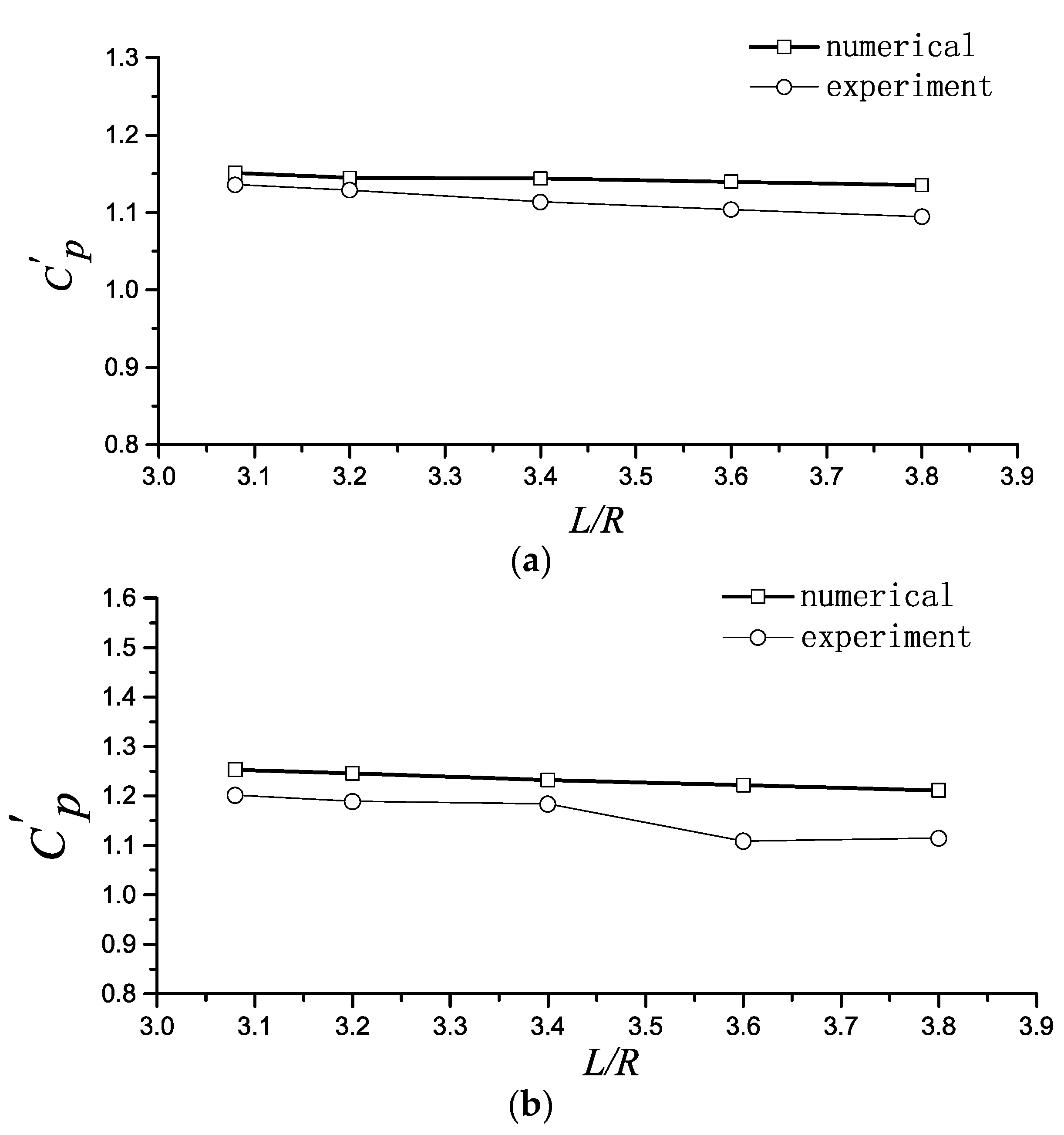
In this paper, the numerical simulation results are compared with models tested in the towing tank. A torque meter to test the total torque of two turbines was used in the model test that was done in laboratory conditions [23,24]. This section covers the double turbine in parallel case conditions; at this moment the mutual interaction of the two turbines are basically the same. Figure 4 shows the comparative results. From the comparison of Figure 4a,b, it can be seen that the two kinds of different tip speed ratios, λ = ωR/V, are similar, and the numerical simulation is approximately in the same direction as the experimental results. Although there is a difference with a maximum error of less than 10%, the numerical simulation would generally reflect the actual situation.
3.3. Analysis of Results
3.3.1. Cases of Ψ = 0°
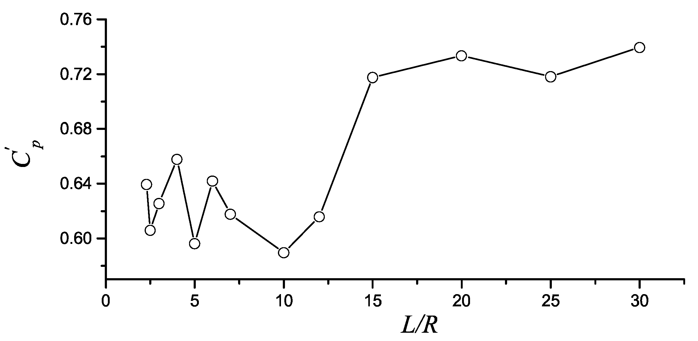
A double turbine series means that the downstream turbine is situated in the wake of the upstream one. In this case, the upstream turbine has an apparent impact on the downstream turbine. Figure 5 shows the way that the relative power coefficient of a double turbine series changes with the turbine spacing, L. The turbine blade profile of the calculation model was NACA0018; the chord length of the blade, C, was 0.06 m; the turbine radius, R, was 0.25 m and Z = 1. As shown in Figure 5, the relative power coefficient of the turbine array increases as the spacing increased, where it rose from 0.6 at L = 2.5R to near 0.75 at L = 30R. There are ups and downs in the data set, and the smaller the turbine spacing is, the more intense the fluctuation. In the case of a turbine in series, the influence of the upstream turbine wake on the downstream one is very large. When the spacing, L, equalled 30R, the overall energy conversion efficiency of the turbine was 75%, which is equal to that of the two separate turbines.
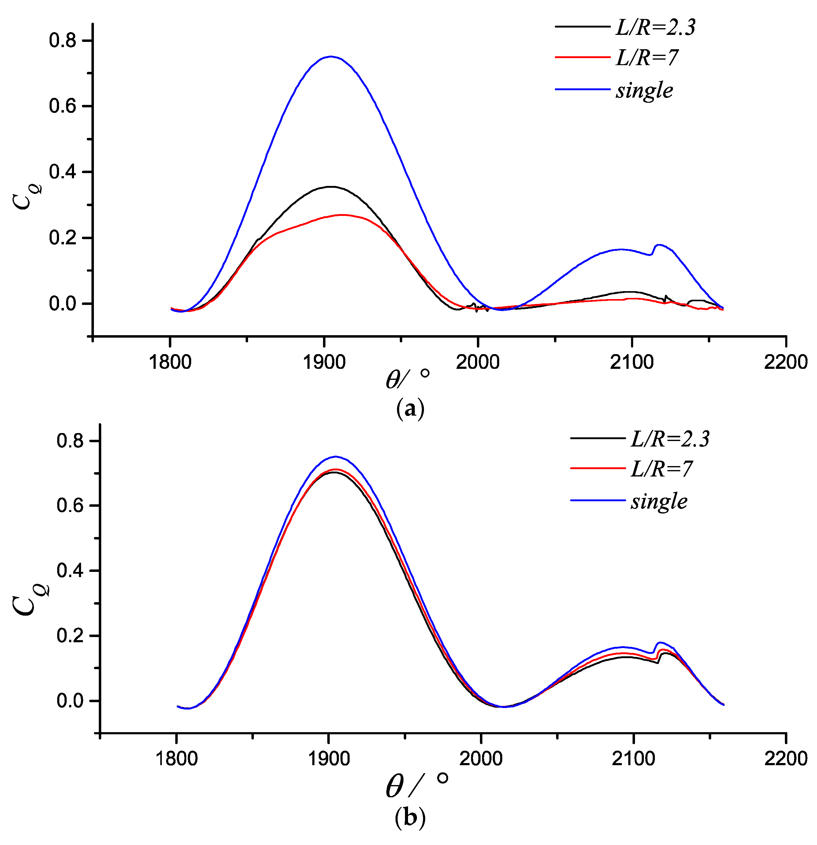
Figure 6 shows the change law for the front and rear turbine torque coefficient as a function of the azimuthal angle and for that of a single turbine torque coefficient under the same conditions. According to the figure, the loss of the total power coefficient of the double turbine array in series was mainly due to the decrease of the downstream turbine efficiency. Figure 6a shows that at the distance of L = 7R, the torque coefficient of the downstream turbine is only about 30% of the single turbine torque coefficient under the same operating conditions, whereas the spacing of the turbine is different and the torque coefficient is different from the distribution of the position angle. Meanwhile, the downstream turbine will also have an impact on the upstream turbine. This effect mainly comes from the presence of downstream turbines that impede the evolution of upstream turbine wake. As is shown in Figure 6b, the torque coefficients of the upstream turbines vary at different intervals. This difference is relatively small compared with the impact of upstream turbines on downstream turbines. The above is for the case of single-blade turbines; with the number of turbine blades increases, the wake produced by a single turbine becomes more complex and the hydrodynamic interaction between turbines increases. Figure 7 shows the change law of the torque coefficient changing with the azimuthal angle in the case of the same turbine size with three blades. As illustrated, the torque coefficient of the upstream turbine is significantly smaller than that of the single turbine, and the torque coefficient of the downstream turbine is lawless with a very small value close to zero.
Compared with a single turbine, the turbine rotor force of a double turbine is also different. Figure 8 shows the contrast between the upstream and downstream turbine rotor and how the force coefficient of the single turbine rotor changes with the azimuthal angle for the case of a three-blade turbine with a tip speed ratio of λ = 2. As illustrated, the torque coefficient of the upstream turbine is smaller than that of the single turbine under the same operating conditions, and the force coefficient of the downstream turbine is significantly smaller than a single turbine in the same working conditions. The variation of the peak and valley values of the downstream turbine torque coefficient with the curve of the azimuthal angle is clear. The azimuthal angle corresponding to the peak and valley values is substantially the same as that of the upstream turbine. However, the whole curve is not smooth, unlike the upstream turbine torque coefficient curve, which is smooth and regular. This shows that the rotor force of the downstream turbine was irregular.
3.3.2. Cases of Ψ = 90°
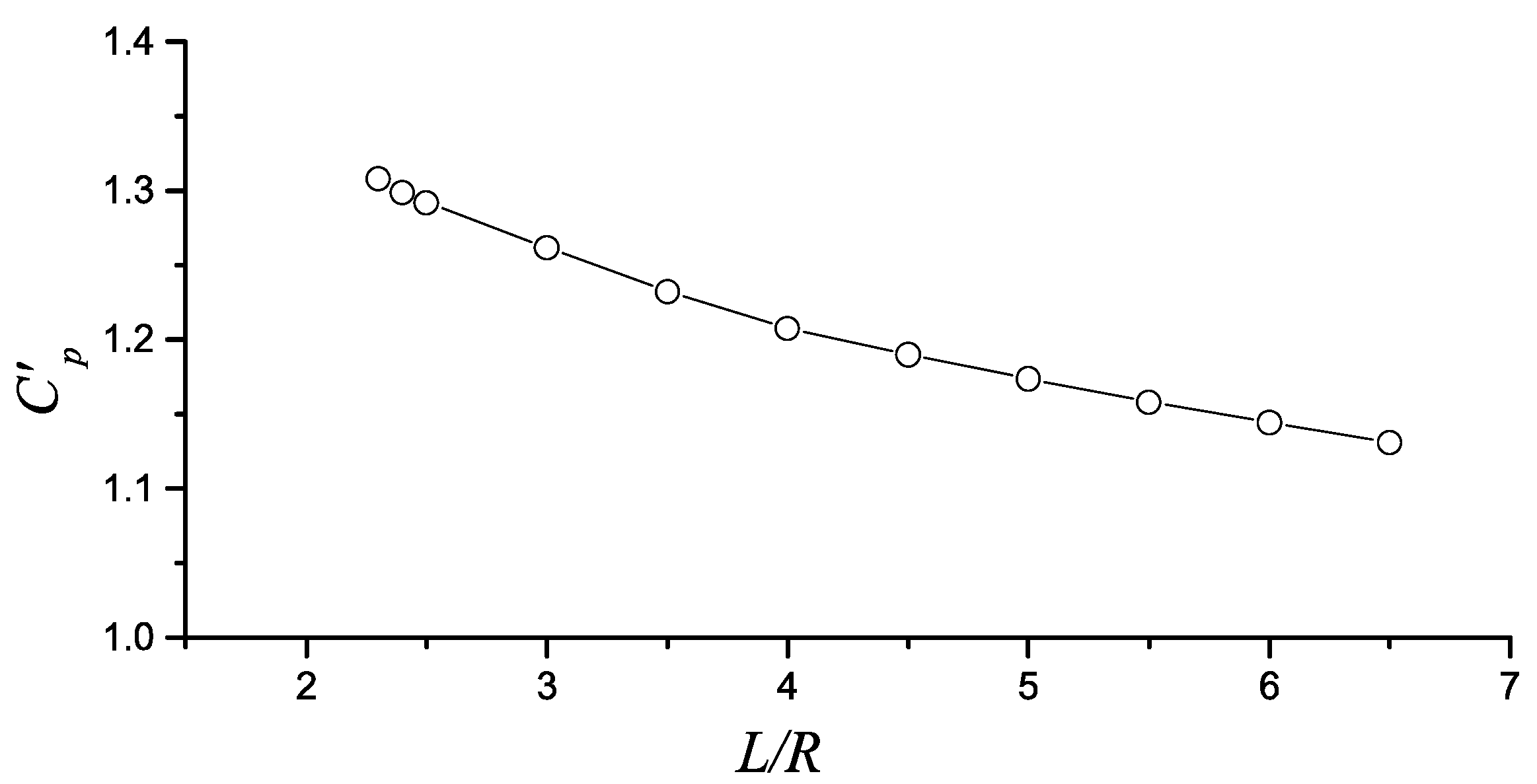
A double turbine parallel means that the axial connections of the two turbines are perpendicular to the direction of flow. In this case, the external load environment of the two turbines was basically the same, and the double turbines were affected by the hydrodynamic interactions from each other. Figure 9 shows how the relative rotation efficiency of the double turbine in parallel changes with the variation of the turbine spacing. The turbine blade profile was NACA0018; the chord length of blade, C, was 0.06 m; the turbine radius, R, was 0.25 m and Z = 3. As can be seen from Figure 9, the smaller the turbine spacing, the greater the relative power coefficient of the parallel turbine array. When the distance between the turbines decreased, the relative power coefficient increases steadily. When L = 6.5R, the power coefficient of the double turbine rose about 13% compared with the two that were independent of each other. When L = 2.3R, this value increased to 31%. From the calculation results, when the turbine was connected in parallel, it effectively improved the overall power coefficient of the turbine array when the two turbine trajectories were very close to each other. The improvement of energy efficiency was beneficial in the development of the tidal energy project. However, the gap between the two turbines is too small to affect the daily maintenance of the turbine generator and the living environment of marine life. Therefore, when developing tidal power, the arrangement of the vertical axis turbine should be fully considered.
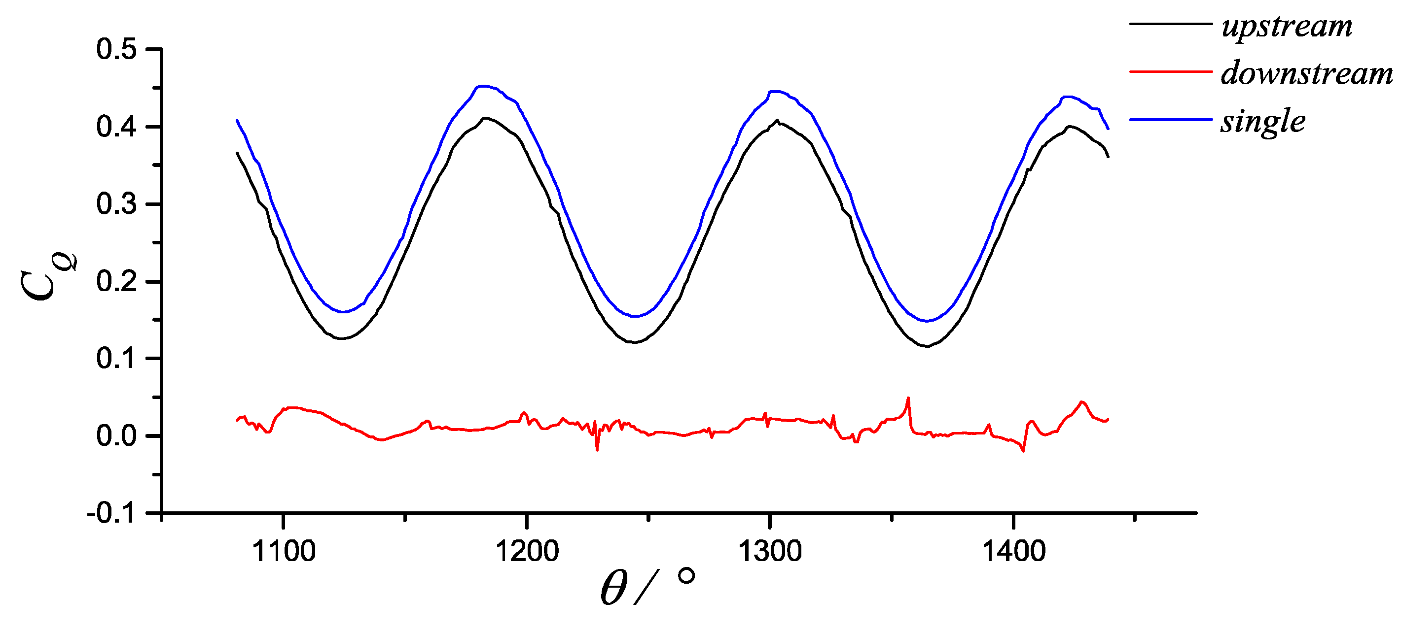
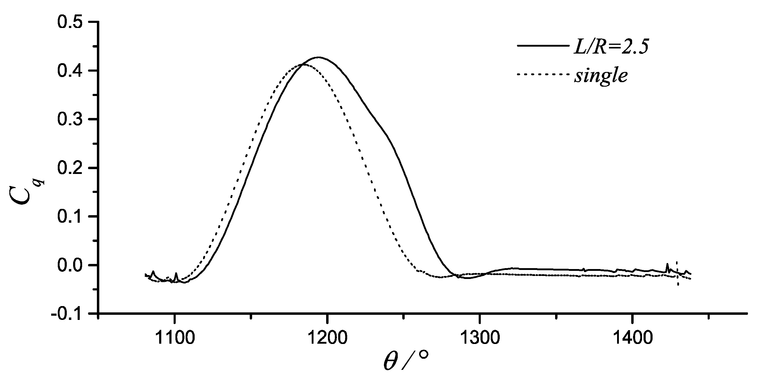
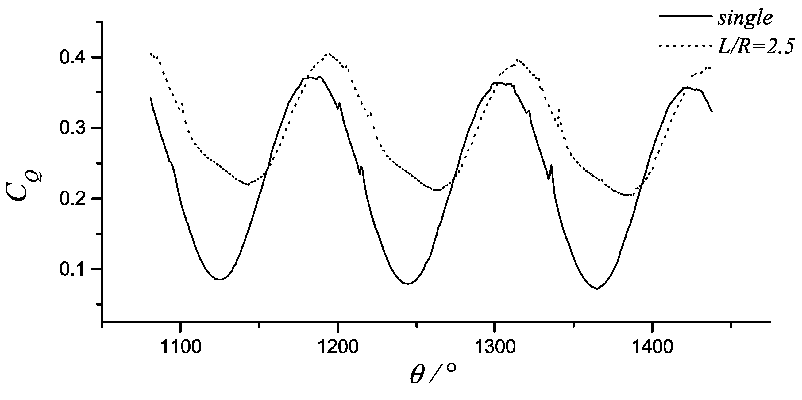
Figure 10 shows the variation curve of the single blade moment coefficient as a function of the azimuthal angle of the parallel turbine array. As shown, if the blade in the upstream disk had an azimuthal angle, θ, from about from 1200° to 1290°, the blade torque coefficient is slightly larger than that of the single turbine. In the downstream disk, the turbine torque coefficient is negative in parallel and stand-alone situations. In parallel, the absolute value of the moment coefficient is small. Compared with the single-blade torque coefficient of the turbine in both parallel and stand-alone situations, it can be seen that the azimuthal angle corresponding to the output area in parallel is larger than that in the single case, and the azimuthal angle which the peak corresponds to is hysteretic.
Figure 11 shows the comparison curve for the turbine rotor torque coefficient as a function of the azimuthal angle in parallel and stand-alone situations. As can be seen from Figure 11, the valley value of the turbine rotor curves in parallel is significantly larger than that in stand-alone situation. In the stand-alone situation, the valley value is around 0.07, and the corresponding valley is close to 0.2 in parallel. The peak in parallel is slightly higher than the stand-alone situation, and the azimuthal angle corresponding to the peak is delayed. Figure 12 shows the information given by the rotor torque coefficient curve of the four-blade turbine in parallel and in the stand-alone case, which is similar to Figure 11. The number of peak and valley of curve of turbine rotor torque coefficient during a rotation period is equal to the number Z. Figure 11 and Figure 12 show that the rotor torque coefficient curve in the stand-alone situation is smoother than the parallel case curve. In case of the double machine, the moment curve has more “burr”. This should be caused by interaction between turbines, and this will affect the stability of the turbine torque output.
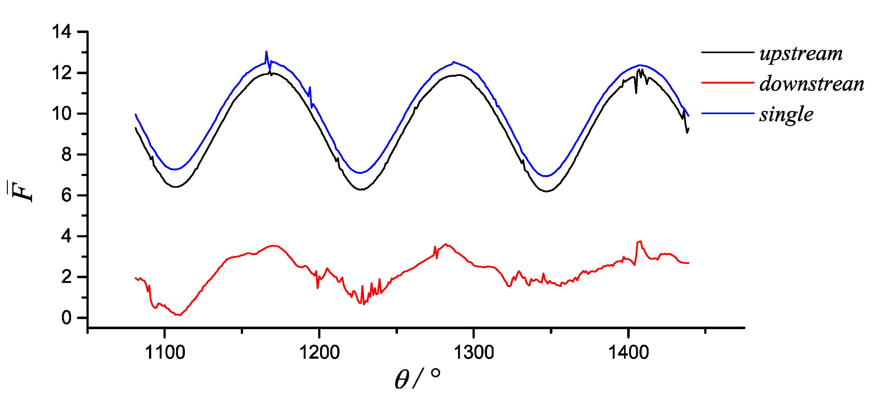
Figure 13 shows the variation law of the parallel turbine and single turbine rotor resultant force coefficient as a function of the azimuthal angle. As shown in Figure 13, when in parallel, the rotor force curve with small fluctuations is more stable than the single case, and the mean is larger than the single. The peak value is larger than that of the turbine in the stand-alone situation, and the valley value is larger than that of the rotor curve. The azimuthal angle of the peak and valley value of the turbine rotor force in parallel is higher than the azimuthal angle corresponding to the peak and valley value in the case of single machine. When the strength of the turbine array is to be checked, the above situation should be fully considered.
3.3.3. Case of Arbitrary Ψ
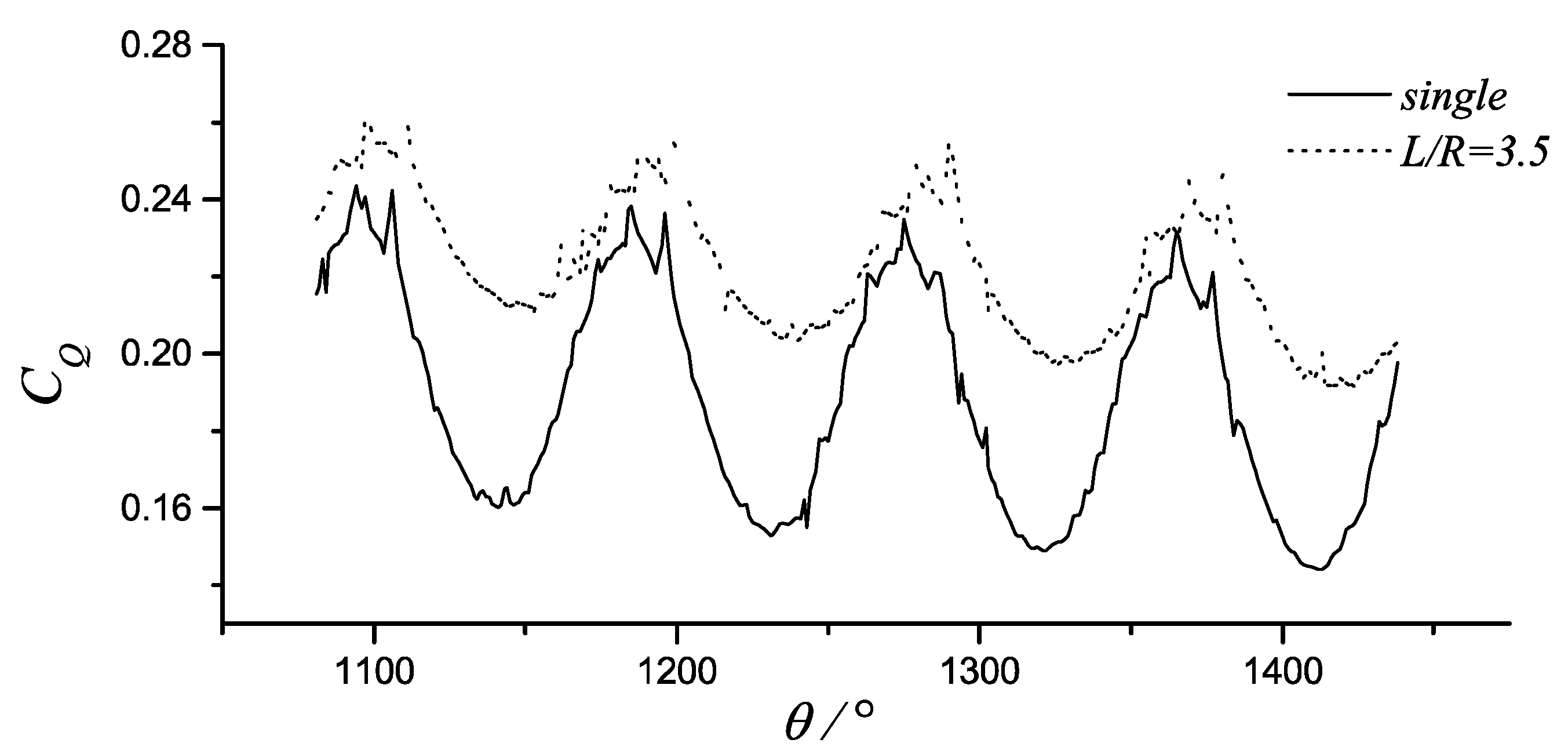
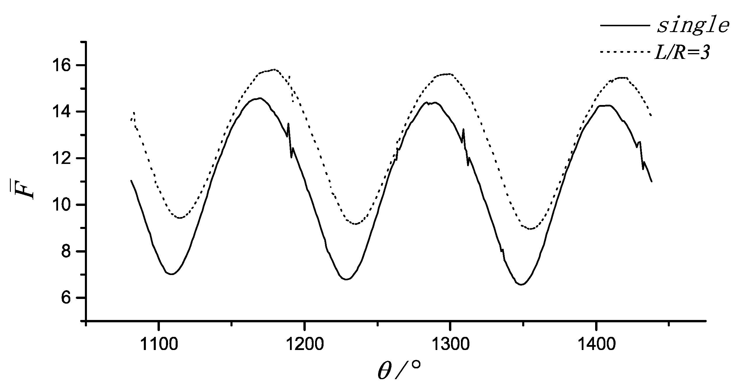
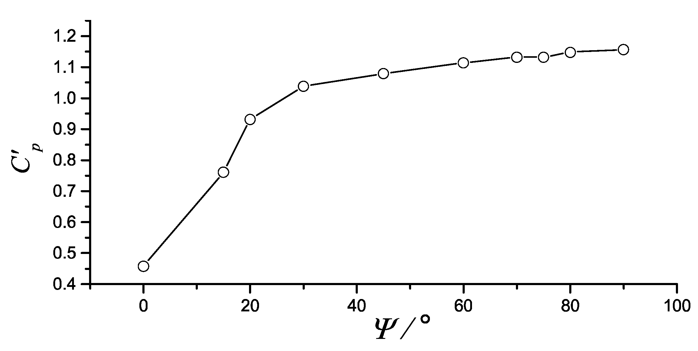
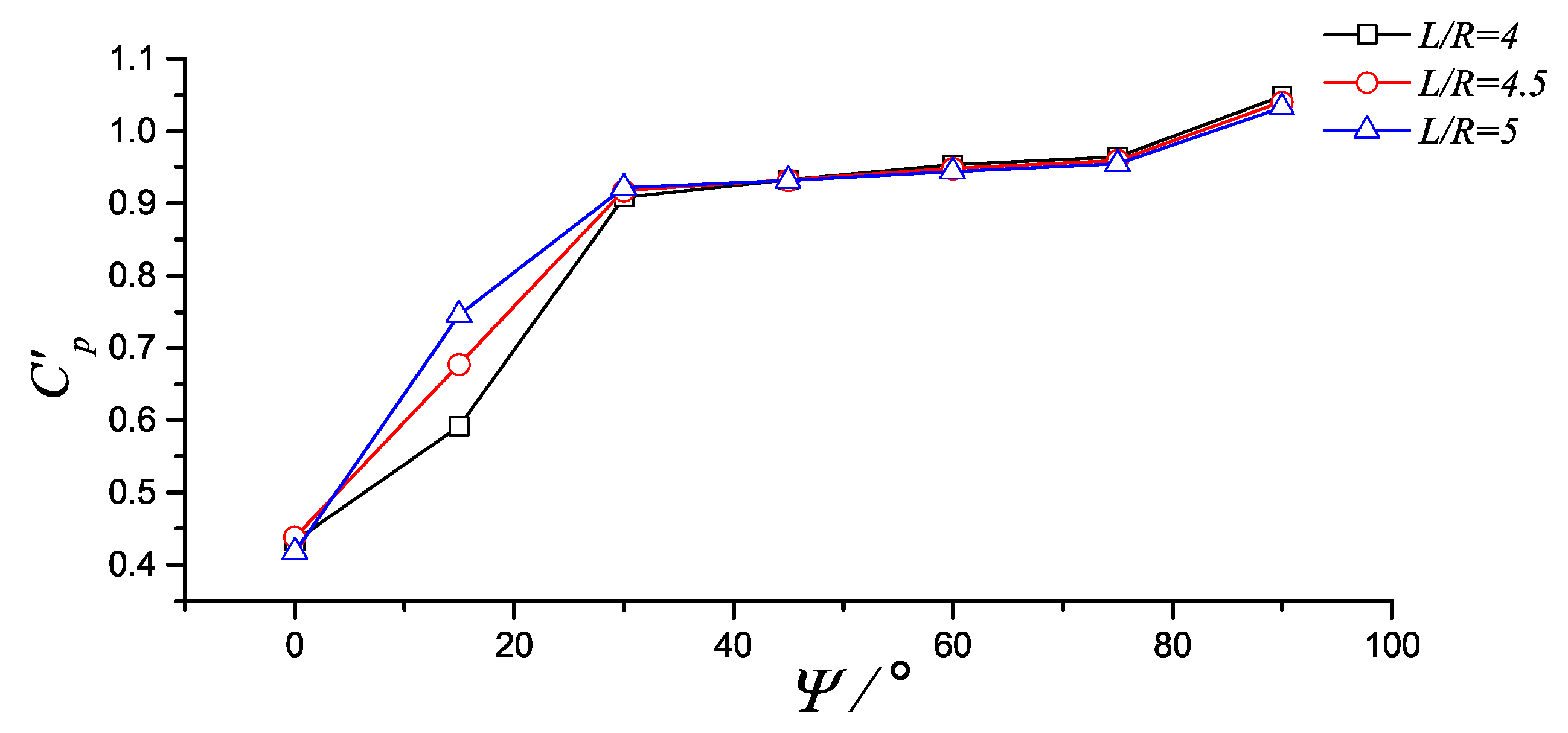
The vertical axis turbines mentioned above in series and parallel are two special cases. Normally, the turbine axis is connected to the direction of the incoming flow at a certain angle. The relative efficiency of the turbine sets with different relative positions was analysed by fixing the distance between the axes of the two turbines and changing the angle between the connecting line of the axis and the direction of the flow. Figure 14 shows the way that the relative efficiency of the three-blade turbine array changed with the declination. The turbine blade profile was NACA0018; the chord length of blade, C, was 0.25 m; and the radius of the blade, R, was 1m. The calculated work condition was λ = 2, the axis spacing was L = 4R and the deflection angle changed from Ψ = 0° to Ψ = 90°. Figure 15 and Figure 16 show the way that the relative power coefficient of the two-blade turbine array changed with the deflection angle. The turbine blade profile was NACA0015; the chord length of blade, C, was 0.125 m; and the radius of the blade, R, was 0.5m. The calculated work condition was λ = 2.4; the axis spacing was L = 2.5R, 3R, 3.5R, 4R, 4.5R, or 5R; and the deflection angle changed from Ψ = 0° to Ψ = 90°. It can be seen from Figure 14 that when the distance between the axis of the two turbines was fixed, the change of relative power coefficient can be divided into two stages, with the deflection angle changing from Ψ = 0° to Ψ = 90°. From Ψ = 0° to Ψ = 30°, the relative power coefficient increases rapidly from 0.45 to 1.05. From Ψ = 30° to Ψ = 90°, the relative power coefficient slowly increases, and the relative efficiency of the turbine in parallel state of the two turbines reaches a maximum of 1.18. In Figure 15 and Figure 16, the variations of the relative efficiency of the turbine array with the deflection angle in the case of six different shaft spacings showed substantially the same information. When comparing the six curves in Figure 15 and Figure 16 for Ψ = 0° to Ψ = 30°, the relative power coefficient values on the different curves corresponding to the same deflection angle are quite different. From Ψ = 30° to Ψ = 90°, the curves tend to be the same exception of two case of L = 3R and L = 2.5R at Ψ = 30°; however, from Ψ = 45° to Ψ = 90°, the curves tend to be quite the same. According to Figure 14, Figure 15 and Figure 16, when considering the arrangement of the turbine, increasing the deflection angle between the turbine axis connecting line and the flow direction appropriately was conducive to the improvement of the overall power coefficient of the turbine array.
4. Conclusions
This paper discussed the law that shows the influence of the turbine wake, spacing, and the deflection angle between the turbine axis connecting line and the flow direction to the overall performance of the hydraulic turbine. At the same time, the blade and the rotor force characteristics were also analysed. The following conclusions can be drawn from the study.
The wake of the vertical axis turbine has a great influence on the performance of the downstream turbine, and in series it will reduce the power coefficient of the downstream turbine greatly. When the turbine array is arranged placing the downstream turbine in exactly the upstream turbine wake it should be avoided as much as possible. When the turbines are connected in parallel, reducing the axis spacing will increase the overall power coefficient of the turbine array. However, the small axis spacing makes installation and routine maintenance more difficult, and the force of the blade and the rotor will increase.
In series (Ψ = 0°), the relative efficiency of the turbine is the smallest, and in parallel (Ψ = 90°), the power coefficient is the highest. In the Ψ = 90°–30° interval, the turbine power coefficient slowly decreased from the maximum, and in the Ψ = 30°–0° interval, the turbine array’s power coefficient quickly dropped to a minimum. Therefore, in the arrangement of the turbine array, the angle between the axis of the double turbine and the direction of the incoming flow should try to avoid the Ψ = −30°–30° interval.
Author Contributions
Conceptualization, G.L.; Methodology, G.L. and Q.C.; Software, G.L. and Q.C.; Formal Analysis, G.L.; Investigation, G.L.; Writing-Original Draft Preparation, G.L.; Writing-Review & Editing, G.L., Q.C. and H.G.; Funding Acquisition, G.L.
Funding
This research was funded by National Natural Science Foundation Program; grant number T (51679216).
Acknowledgments
The study is supported by National Natural Science Foundation Program.
Conflicts of Interest
The authors declare no conflict of interest.
Nomenclature
| BEMT | Blade Element Momentum Theory |
| CFD | Computational Fluid Dynamics |
| LES | Large Eddy Simulation |
| RANS | Reynolds Average Navier-Stokes |
| BEMT | Blade Element Momentum Theory |
| Xd, Yd | coordinate spacing of the rotation centers of turbines in twin-turbine system |
| angle between the connection of the rotation centers of turbines and the X axis | |
| L | distance of the rotation centers of turbines |
| t | time |
| t0 | initial time |
| Ω | rotating angular velocity about the origin o |
| U | translational velocity of the origin o |
| V | velocity of uniform incoming flow at infinity |
| θ | azimuthal angle |
| rotating angular velocity about the rotation center of turbine | |
| velocity potential | |
| fluid domain | |
| perturbation velocity potential | |
| P | pressure on the blade surface |
| f | force on the blade |
| q | moment of the blade |
| Cq | moment coefficient of a single blade on turbine |
| F | hydrodynamic force acting on the turbine |
| Q | hydrodynamic torque acting on the turbine rotor shaft |
| resultant force coefficient of the turbine | |
| CQ | average torque coefficient of the turbine rotor shaft |
| CP | power coefficient of the turbine |
| D | diameter of turbine |
| R | radius of turbine |
| b | wingspan length of blade |
| C | chord length of blade |
| Z | blade number of a single turbine |
| λ | tip speed ratios |
| relative power coefficient of double turbines array |
References
- Yang, M.; Pation-Echeverri, D.; Yang, F. Wind power generation in China: Understanding the mismatch between capacity and generation. Renew. Energy 2012, 41, 145–151. [Google Scholar] [CrossRef]
- Yu, J.; Ji, F.; Zhang, L. An over painted oriental arts: Evaluation of the development of the Chinese renewable energy market using the wind power market as a model. Energy Policy 2009, 37, 5221–5225. [Google Scholar] [CrossRef]
- Li, Z. Numerical Simulation and Experimental Study on Hydrodynamic Characteristic of Vertical Axis Tidal Turbine. Ph.D. Thesis, Harbin Engineering University, Harbin, China, 2011. [Google Scholar]
- Bahaj, A.S. Generating electricity from the oceans. Renewable Sustainable Energy Rev. 2011, 15, 3399–3416. [Google Scholar] [CrossRef]
- Westwood, A. SeaGen installation moves forward. Renew. Energy Focus 2008, 9, 26–27. [Google Scholar] [CrossRef]
- Westwood, A. Ocean power: Wave and tidal energy review. Refocus 2004, 5, 50–55. [Google Scholar] [CrossRef]
- Open Centre Turbine. Available online: http://www.openhydro.com/Technology/Open-Centre-Turbine (accessed on 7 May 2017).
- Ocean energy technology: The Davis Hydro Turbine. Refocus 2001, 2, 44–47. [CrossRef]
- Lago, L.I.; Ponta, F.L.; Chen, L. Advances and trends in hydrokinetic turbine systems. Energy Sustainable Dev. 2010, 14, 287–296. [Google Scholar] [CrossRef]
- Sathit, P.; Chaiwat, K.; Yodchai, T. Experimental investigation of helical tidal turbine characteristics with different twists. Energy Procedia 2015, 79, 409–414. [Google Scholar]
- Zhou, Z.; Benbouzid, M.; Charpentiera, J.F. Developments in large marine current turbine technologies—A review. Renewable Sustainable Energy Rev. 2017, 71, 852–858. [Google Scholar] [CrossRef]
- Coiro, D.P.; Nicolosi, F.; De Marco, A.; Melone, S.; Montella, F. Dynamic behavior of the patented kobold tidal current turbine: Numerical and experimental aspects. Acta Polythecnica Int. J. 2005, 45, 77–84. [Google Scholar]
- Guo, F. Performance Analysis of Vertical-Axis Tidal Current Turbines and Optimizing Turbines Array. Ph.D. Thesis, Dalian University of Technology, Dalian, China, 2013. [Google Scholar]
- Bai, L.; Spence, R.R.G.; Dudziak, G. Investigation of the influence of array arrangement and spacing on Tidal Energy Converter (TEC) performance using a 3-dimensional CFD model. In Proceedings of the 8th European Wave and Tidal Energy Conference, Uppsala, Sweden, 7–10 September 2009. [Google Scholar]
- Churchfield, M.J.; Li, Y.; Moriarty, P.J. A large-eddy simulation study of wake propagation and power production in an array of tidal-current turbines. In Proceedings of the 9th European Wave and Tidal Energy Conference, Southhampton, UK, 4–9 September 2011. [Google Scholar]
- Turnock, S.R.; Phillips, A.B.; Banks, J. Modelling tidal current turbine wakes using a coupled RANS-BEMT approach as a tool for analyzing power capture of arrays of turbines. Ocean Eng. 2011, 38, 1300–1307. [Google Scholar] [CrossRef]
- Antheaume, S.; Maitre, T.; Achard, J.L. Hydraulic Darrieus turbines efficiency for free fluid flow conditions versus power farms conditions. Renew. Energy 2008, 33, 2186–2198. [Google Scholar] [CrossRef]
- Li, Y.; Calisal, S.M. Preliminary investigation of power output of two typical two-turbine tidal current systems. In Proceedings of the ASME Conference, New York, NY, USA, 31 May–5 June 2009. [Google Scholar]
- Goude, A.; Agren, O. Numerical simulation of a farm of vertical axis marine current turbines. In Proceedings of the ASME 29th International Conference on Ocean, Offshore and Arctic Engineering, Shanghai, China, 6–11 June 2010. [Google Scholar]
- Gebreslassie, M.G.; Tabor, G.R.; Belmont, M.R. Investigation of the performance of a staggered configuration of tidal turbines using CFD. Renew. Energy 2015, 80, 690–698. [Google Scholar] [CrossRef] [Green Version]
- Zanforlin, S.; Burchi, F.; Bitossi, N. Hydrodynamic interactions between three closely-spaced Vertical Axis Tidal Turbines. Energy Procedia 2016, 101, 520–527. [Google Scholar] [CrossRef]
- Giorgetti, S.; Pellegrini, G.; Zanforlin, S. CFD investigation on the aerodynamic interferences between medium-solidity Darrieus Vertical Axis Wind Turbines. Energy Procedia 2015, 81, 227–239. [Google Scholar] [CrossRef]
- Li, G.; Wu, W.; Xie, Y. Analysis of hydrodynamic performance of vertical-axis tidal-current turbine with experiment in towing tank. Shipbuild. Chin. 2014, 55, 143–148. [Google Scholar]
- Xie, Y.; Li, G.; Zhang, Z. Experimental analysis on arrangement rule of the twin-turbine systems with vertical axis tidal current turbines. Acta Energiae Solaris Sin. 2017, 38, 537–542. [Google Scholar]
Figure 1.
The model of twin-turbine system and the important parameters.

Figure 2.
Schematic diagram of blade motion and the local coordinate system.

Figure 3.
Central path of trailing vortices of turbine array; tip speed ratio λ = 2. The mutual interference of wake of the turbines is shown. (a) Three turbines in “-” type arrangement; (b) Three turbines in “Z” type arrangement.
Figure 3.
Central path of trailing vortices of turbine array; tip speed ratio λ = 2. The mutual interference of wake of the turbines is shown. (a) Three turbines in “-” type arrangement; (b) Three turbines in “Z” type arrangement.

Figure 4.
The variation of relative power coefficient with turbine spacing of double turbines in parallel connection. (a) λ = 1.7; (b) λ = 2.75.
Figure 4.
The variation of relative power coefficient with turbine spacing of double turbines in parallel connection. (a) λ = 1.7; (b) λ = 2.75.

Figure 5.
The changes of power coefficient with spacing where the tip speed ratio λ = 2.

Figure 6.
Influence of spacing on turbine moment coefficient where Z = 1. (a) The impact on downstream turbine; (b) The impact on upstream turbine.
Figure 6.
Influence of spacing on turbine moment coefficient where Z = 1. (a) The impact on downstream turbine; (b) The impact on upstream turbine.

Figure 7.
Influence of spacing on turbine moment coefficient where Z = 3 and λ = 2.

Figure 8.
The force of the rotor varies with the azimuthal angle in the case of double turbines in series where Z = 3 and λ = 2.
Figure 8.
The force of the rotor varies with the azimuthal angle in the case of double turbines in series where Z = 3 and λ = 2.

Figure 9.
The relative power coefficient varies with the spacing in parallel connection where λ = 2.5.
Figure 9.
The relative power coefficient varies with the spacing in parallel connection where λ = 2.5.

Figure 10.
The variation law of single blade moment coefficient with azimuthal angle in parallel turbine where λ = 2.5.
Figure 10.
The variation law of single blade moment coefficient with azimuthal angle in parallel turbine where λ = 2.5.

Figure 11.
The comparison of the turbine torque coefficient in the parallel and single situation where Z = 3.
Figure 11.
The comparison of the turbine torque coefficient in the parallel and single situation where Z = 3.

Figure 12.
The comparison of the turbine torque coefficient in the parallel and single situation where Z = 4.
Figure 12.
The comparison of the turbine torque coefficient in the parallel and single situation where Z = 4.

Figure 13.
The comparison of the turbine resultant force coefficient in the parallel and single situation where Z = 3 and λ = 2.5.
Figure 13.
The comparison of the turbine resultant force coefficient in the parallel and single situation where Z = 3 and λ = 2.5.

Figure 14.
Influence of deflection angle on hydrodynamic characteristics of hydraulic turbine where Z = 3 and L = 4R.
Figure 14.
Influence of deflection angle on hydrodynamic characteristics of hydraulic turbine where Z = 3 and L = 4R.

Figure 15.
Influence of deflection angle on hydrodynamic characteristics of hydraulic turbine where Z = 2.
Figure 15.
Influence of deflection angle on hydrodynamic characteristics of hydraulic turbine where Z = 2.

Figure 16.
Influence of deflection angle on hydrodynamic characteristics of hydraulic turbine where Z = 2.
Figure 16.
Influence of deflection angle on hydrodynamic characteristics of hydraulic turbine where Z = 2.

© 2018 by the authors. Licensee MDPI, Basel, Switzerland. This article is an open access article distributed under the terms and conditions of the Creative Commons Attribution (CC BY) license (http://creativecommons.org/licenses/by/4.0/).
Share and Cite
MDPI and ACS Style
Li, G.; Chen, Q.; Gu, H. Study of Hydrodynamic Interference of Vertical-Axis Tidal Turbine Array. Water 2018, 10, 1228. https://doi.org/10.3390/w10091228
AMA Style
Li G, Chen Q, Gu H. Study of Hydrodynamic Interference of Vertical-Axis Tidal Turbine Array. Water. 2018; 10(9):1228. https://doi.org/10.3390/w10091228
Chicago/Turabian StyleLi, Guangnian, Qingren Chen, and Hanbin Gu. 2018. "Study of Hydrodynamic Interference of Vertical-Axis Tidal Turbine Array" Water 10, no. 9: 1228. https://doi.org/10.3390/w10091228
Note that from the first issue of 2016, this journal uses article numbers instead of page numbers. See further details here.