
Abstract
Rechargeable lithium-based batteries are one of the key enabling technologies driving the shift to renewable energy, and research into novel technologies has intensified to meet growing demands in applications requiring higher energy and power density. The mechanisms behind battery degradation can be investigated across multiple length-scales with X-ray imaging methods; at the nano-scale severe constraints are imposed on sample size in order to obtain adequate signal to noise. Here, we present a novel laser-milling technique to prepare geometrically optimal samples for X-ray nano-tomography. Advantages of this technique include significantly reduced sample preparation time, and a suitable geometry for mosaic acquisition, enabling a larger field of view to be captured at high spatial resolution, thus improving statistics. The geometry of the resulting electrode remains highly suitable for nano-tomography, and yet permits in situ and operando experiments to be carried out on standard electrode coatings, providing new insights into transient phenomena whilst closely mimicking standard electrochemical cells.
Export citation and abstract BibTeX RIS

This is an open access article distributed under the terms of the Creative Commons Attribution 4.0 License (CC BY, http://creativecommons.org/licenses/by/4.0/), which permits unrestricted reuse of the work in any medium, provided the original work is properly cited.
The rising demand for portable power sources with high energy densities has generated unprecedented levels of interest in Li-ion and post-Li-ion rechargeable battery technologies, which include lithium-sulfur (Li-S) and lithium-air (Li-air) batteries. These cell chemistries exist in various stages of commercialisation: whilst Li-ion batteries are the state-of-the-art technology within the commercial domain, Li-S and Li-air batteries have the potential to surpass their energy density by an order of magnitude; however, they suffer from increased rates of degradation that have thus far impeded successful commercialization.
All batteries inevitably degrade during their storage and operation, resulting in reduced electrical and Coulombic efficiencies and a finite cycle life. These degradation processes arise from numerous factors that may be induced or exacerbated by heterogeneities within the cell. These heterogeneities cascade to the cell level (ca. centimetres) across multiple length-scales from atomic-level defects within the primary particles (ca. 0.1 nm), to grain defects within primary and secondary particles (ca. 10 s of nm), and microstructural defects within whole electrodes (ca. 0.1 to 10 μm).
Numerous advanced materials characterisation methods have been applied to gain a better understanding of the reaction mechanisms and causes of degradation within batteries at various length-scales: these typically involve measurements using X-ray, neutron, or electron probes. In addition to bulk characterisation where measurements are averaged across an entire region of the sample illuminated by the probe, it is possible to obtain spatially resolved information with either area detectors or through scanning probe-type measurements where the sample is rastered through the probe whilst encoders record the spatial position of the sample. Tomographic reconstruction may also be possible if a rotation axis is added to the sample stage and measurements are performed over sufficient viewing angles.
Given the numerous permutations of possible configurations, sample preparation may be highly challenging depending on the requirements of the technique involved, and there is generally a trade-off between sample size, field of view and spatial resolution achievable. Area detectors employed for imaging are typically a few thousand pixels across (i.e. a 1 K detector with 1024 horizontal pixels would equate to a field of view of 65 μm for a 64 nm pixel size) and whilst it is theoretically possible to have an arbitrarily large number of points for scanning probe measurements, the quantity of data generated would be unfeasibly large to process and analyse and the signal collected per pixel would be too low.
Close to the diffraction limit for conventional bright field imaging at X-ray wavelengths (ca. 1 nm to 0.1 nm) is transmission X-ray microscopy (TXM) and its three-dimensional equivalent X-ray nano-tomography (nano-CT), where nano-scale characterisation is achievable through advanced X-ray optics.1–5 In addition to the field of view constraints described earlier, X-ray transmission at a given probe energy (ca. 5 to 15 keV in the case of nano-CT) is dependent on the thickness and mass density of a sample which can be quantified in terms of a linear attenuation coefficient (in cm−1). Thus, to obtain an adequate signal to noise ratio and to fit within the fixed field of view of nano-CT, the overall thickness of the sample has to be tuned accordingly, and sub-100 μm sample diameters are not uncommon.
Our group have previously adapted a laser micro-machining technique, used in numerous applications,6,7 to mill delicate battery electrode samples down to ca. 100 μm in diameter or smaller.8 For Li-ion batteries, these electrodes are typically composed of either transition metal oxide (positive electrode) or graphite (negative electrode) embedded in a conductive carbon and polymeric binder domain and coated on metal foils. The cylindrical geometry of the samples prepared with this technique is highly suited to various in situ and operando studies, including in situ compression measurements.9
Here, we propose an alternative sample preparation strategy that produces nano-CT samples smaller than 100 μm in size with turnaround time of less than 1 min per sample. In addition to rapid sample preparation, advantages of the laser-milling technique include the ability to perform vertical stitching of multiple tomograms, mosaic acquisition (which allows the acquisition of samples of larger diameters at high resolution), and highly localized laser-induced sample damage due to the low overall dose and minimal sample heating.
Methodology
Laser milling and lathing of electrode samples
Lithium nickel manganese cobalt oxide (NMC811, NEI Corporation) positive Li-ion electrode samples were secured on a petri dish with polyimide tape and fixed to the translation table of a laser micro-machining instrument (A Series, Oxford Lasers Ltd.) containing a 532 nm laser with a spot size of ca. 40 μm. The electrodes were mounted with the current collector facing up to minimize damage to the delicate electrode surface. Where it is desirable to keep the electrodes in a protective atmosphere, the petri dish can be sealed under argon with a glass lid—its optically transparent nature allows transmission of the laser beam with minimal distortion. The laser was programmed to mill a series of lines amounting to a tab with customizable dimensions and the electrode was cut at a speed of ca. 2 mm s−1. The resulting tabs consisted of 2 rectangular sections with the smaller section measuring ca. 0.1 mm × 0.5 mm and the larger section measuring ca. 1.5 mm × 4 mm. Optimization of laser power and milling speed is sample and instrument dependent, and some trial and error is required with the goal of minimizing laser power (to avoid unnecessary beam-included sample damage) whilst obtaining a clean cut. For comparison, a ca. 80 μm diameter electrode pillar of the same NMC811 electrode sample was prepared with the same technique as previously described8 using a low laser power.
Electrochemical characterisation of tab electrodes
The laser-cut electrode tabs as described above were dried for 12 h under vacuum at 120 °C in a glass drying oven (B-585, BUCHI Ltd.) before being assembled into coin cells (CR2032, Hohsen Corp.). A half-cell electrode arrangement was used with the NMC811 tab electrode as the working electrode and lithium metal (MTI Corp) as the counter electrode. A tri-layer polyolefin membrane was used as separator (Celgard 2325, Celgard, LLC.) and the electrolyte used was 1.0 M lithium hexafluorophosphate in ethylene carbonate and ethyl methyl carbonate (1.0 M LiPF6 in EC:EMC (3:7 v/v), Soulbrain MI).
The theoretical capacity of the CR2032 cells was calculated to be ca. 0.121 mAh, based on the mass loading and area of the electrode, and a specific capacity of 190 mAh g−1. The cells were taken through 3 initial cycles using a constant-current-constant-voltage (CC-CV) charge and constant-current (CC) discharge protocol. The current used during the constant current steps was equivalent to a C/20 rate with a cut-off condition of 4.2 V for charge and 2.5 V for discharge. For the constant-voltage charge step, the cells were held at 4.2 V until the current dropped to C/40. Following the initial cycles, a rate capability test was performed on the cells by taking them through various C-rate regimes from C/10 to 2 C and back to C/10, (C/10, C/5, C/2, 1 C, 2 C) for 5 cycles at each C-rate. The same cut-off conditions were used. For comparison, the same electrodes were punched into 15 mm discs, assembled into CR2032 coin cells with the same arrangement and cycled for the 3 initial cycles described above. All electrochemical tests as shown in the figures in the Results section were performed on a multi-channel battery cycler (BCS-805, Bio-Logic SAS).
Sample mounting and X-ray nano-tomography
The pristine laser-cut electrode tabs were mounted on steel dressmakers' pins using a quick setting epoxy (ITW Devcon 5 minute. Epoxy, ITW Devcon) and were left to set over a 24 h period to minimize sample movement. Ex situ X-ray nano-computed tomography (CT) was performed on the laser-milled tab electrode samples using a lab-based nano-CT instrument (ZEISS Xradia 810 Ultra, Carl Zeiss Inc.) containing a rotating Cr anode source set to an accelerating voltage of 35 kV. The beam was quasi-monochromatized at the Cr-Kα emission line of 5.4 keV by a capillary condenser, illuminating the sample with a hollow cone beam focused on the sample, with a Fresnel zone plate as the objective element creating a magnified image on a 1024 × 1024 pixel CCD detector.10
The lab-based configuration of the ZEISS Xradia 810 Ultra X-ray microscope offers two imaging modes, absorption and Zernike phase contrast, and two fields of view: either a 65 μm FOV with a pixel size of 64 nm or a 16 μm FOV with a pixel size of 16 nm. Large field of view mode with a pixel binning of 1 was used, resulting in a pixel size of ca. 64 nm and a field of view of ca. 65 μm. The sample was rotated through 180° with radiographs collected at discrete angular intervals amounting to 1601 projections. The sample was translated by ca. 58 μm in the vertical direction after the acquisition of each tomogram to obtain four tomograms with overlapping regions of ca. 6 μm between each tomogram.
For comparison, the laser-milled electrode pillar as described previously was also imaged with the same imaging parameters, although no stitching was carried out as the sample was fully within the vertical field of view.
The projection data from each tomogram were reconstructed with proprietary reconstruction software (XMReconstructor, Carl Zeiss Inc.) using a parallel beam reconstruction algorithm.
Vertical stitching of nano-CT datasets
The four reconstructed tomograms were manually registered by visually aligning the datasets using the Avizo image processing software (2019.2, Thermo Fisher Scientific). The registered tomograms were then merged using the "Merge" module in Avizo to form a combined volume. To ensure that the virtual slices captured from the dataset were orthogonal to the electrode, the combined volume was transformed to correct for sample tilt. The transformed volume was resampled using a Lanczos filter11 producing a final volume that contained 683 × 903 × 1981 voxels.
Image processing
Image processing was performed in Avizo on the final transformed volume containing 683 × 903 × 1981 voxels. As the aluminium current collector had similar grayscale values to the NMC particles, a sub-volume was extracted with the current collector cropped out. Segmentation was then carried out via a simple thresholding algorithm derived from Otsu's method12 and available in the "Auto-Threshold" module in Avizo. Small features less than 5 voxels wide were removed and the "Separate Objects" Avizo module was applied to separate neighbour particles that were in contact with one another. Particles that were only partially captured within the volume were removed using the "Border Kill" module and finally, the remaining particles were individually labelled using the "Label Analysis" Avizo module which assigns different label values to each particle.
For comparison, the same image analysis workflow was carried out on the reconstructed electrode pillar obtained with the laser-lathing technique, where the tomogram contained 1004 × 1024 × 1013 voxels (although the useable volume was smaller as the vertical height of the detector was not fully utilized).
Results
Most optical components within the TXM architecture, as presented in Fig. 1, are common to both synchrotron and lab-based X-ray sources, the major differences arise from the higher flux attainable and tuneable probe energy when using synchrotron light sources.
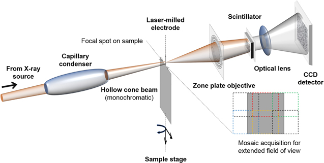
Figure 1. Transmission X-ray microscopy architecture showing Fresnel zone plate objective.
Download figure:
Standard image High-resolution imageIn general, sample preparation for nano-CT can be challenging for both low-Z and high-Z materials because the transmission required for a high contrast-to-noise ratio (CNR) falls within a relatively narrow band13 and is further constrained by the fixed energy of lab-based X-ray sources. For an ideal charge-coupled device (CCD) detector, where photon noise is directly proportional to the square root of intensity incident on the detector, Reiter et al. calculated the CNR to be at its theoretical maximum at about 14% transmission (or e2 ≈ 0.14).
The attenuation lengths for common battery materials within the range of X-ray energies used for nano-CT are presented in Fig. 2, assuming a fully solid, non-porous and uniform sample. As the attenuation length is the thickness at which the intensity of the transmitted beam falls to 1/e of the incident beam, the optimal sample thickness giving an ideal transmission of ca. 14% (or e2 ≈ 0.14) for a high CNR is simply double the attenuation length at any given photon energy presented in Fig. 2. This clearly highlights the small sample sizes required to attain adequate transmission, especially for transition metal oxide positive electrode materials (NCA, LFP, NMC and LCO for example). Step changes in attenuation length can be seen in Fig. 2 for the transition metal oxides and these correspond to the absorption at the K-edge of each transition metal of interest, Co, Ni, Fe and Mn.

Figure 2. Attenuation lengths where the ratio between the incident beam and the transmitted beam, or transmission, falls to 1/e (ca. 36.8%) for (a) common current collector materials and graphitic carbon and (b) common positive electrode materials in Li-ion and Li-S batteries.14
Download figure:
Standard image High-resolution imageAlthough a useful rule of thumb in determining sample thickness requirements, it should be considered that the actual attenuation length of an electrode may be underestimated in Fig. 2 as the inherent porosity of active material particles and the volume fraction of the electrode sample not containing active material is unaccounted for. Other considerations that influence the contrast to noise ratio include: interior tomography artefacts arising from region-of-interest scans, should the sample thickness required be larger than the field of view15; insufficient pixel intensities where exposure time is reduced; and insufficient angular projections.
Laser-milling technique
As described in the introduction and illustrated in Figs. 3 and 4a, we have previously adapted a laser-milling technique to lathe battery electrode pillar samples to sizes suitable for nano-CT.8 With the original sample geometry shown in Fig. 4a, the current collector of the electrode is orthogonal to the centre of rotation of the sample and does not obscure the electrode layer in any of the angular projections. Whilst this is ideal for electrodes with highly attenuating current collectors (i.e. copper or nickel), and for experiments outlined earlier such as in situ compression tests to mimic calendaring,9 potential drawbacks include heat-induced sample damage, long sample preparation time and limited imaging volume. From previous attempts, it has been found that the laser-milling technique may not be suited to samples with a low melting point or susceptible to sublimation, for instance sulfur electrodes used in Li-S cells.16,17

Figure 3. (a) Conventional electrode pillar preparation technique and (b) New electrode tab preparation technique.
Download figure:
Standard image High-resolution image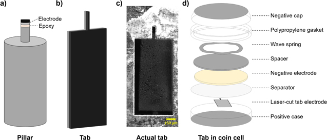
Figure 4. Potential sample geometries that can be achieved with laser-milling, including (a) conventional pillar-shaped electrode mounted on a dowel pin, (b) tab-shaped electrode and (c) the same tab-shaped geometry cut from an actual electrode. (d) A schematic of the tab electrode in a coin cell.
Download figure:
Standard image High-resolution imageFurthermore, attempting to introduce laser-milled electrode pillars into in situ environments remains challenging due to various factors. Samples are often mounted onto stainless steel pins with epoxy before being milled into suitable sizes for nano-CT. Epoxy is generally electrically insulating, preventing the passage of current to the electrode, and whilst certain grades of conductive epoxy may be used, the conducting material may not be electrochemically inert, which would influence the validity of the electrochemical data obtained.
For electrodes with lower-Z current collectors (i.e. aluminium, as commonly employed in Li-ion positive electrodes), it is possible to prepare samples for nano-CT with geometries where the current collector is parallel to the centre of rotation of the sample. We have previously prepared wedge-shaped samples using a sharp scalpel for imaging NMC electrodes using micro-CT,18 achieving a spatial resolution capable of resolving the carbon binder domain (CBD). However, current collector delamination is a severe issue with manual preparation of battery electrodes for imaging, especially for samples that have undergone extensive ageing. Other drawbacks of manual preparation include poorer control of sample geometry and the possibility that the morphology of the sample is influenced by the force exerted by the cutting blade.
A laser micro-machining instrument with micron-level precision was therefore adapted to cut electrodes to sizes suitable for nano-CT. The difference between the conventional laser electrode pillar preparation and new laser tab preparation technique is illustrated in Fig. 3. The tab-shaped geometry of the cut electrode is presented in Fig. 4b, and the high precision attainable with laser cutting is observable in Figs. 4c and 5, which is a mosaic radiograph of a cycled NMC electrode from which a tab was prepared for nano-CT. As the spot size of the laser beam used is approximately 40 μm, a nominal tab width of 100 μm would result in a tab of ca. 80 μm in width, which is an ideal size that approximately fits within the field of view of the ZEISS Xradia 810 Ultra in large field of view (LFOV) mode.
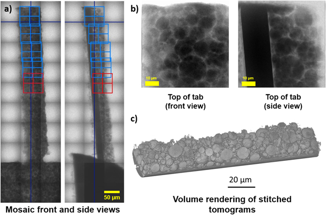
Figure 5. (a) Mosaic front and side radiographs of the NMC electrode tab where the field of view of each blue or red is ca. 65 μm. (b) A front and side radiographs at the top of the NMC tab and (c) a volume rendering of the stitched tomograms acquired from the electrode.
Download figure:
Standard image High-resolution imageIt is thus conceivable for the same electrode to be imaged with lab-based nano-CT at its pristine state before being assembled into standard CR2032 coin cells (as illustrated in Fig. 4d) for cycling due to the unique geometry of the electrode tab. The coin cells may then be disassembled after cycling for post-mortem imaging, facilitating time-resolved studies where the same particles may be tracked as a function of cycle life. The advantages of this proposed workflow will be demonstrated in a later section, where virtually no impact on electrochemical performance is observed when compared to coin cells containing standard 15 mm electrodes.
In addition, whilst ex situ investigations are unable to capture dynamic processes occurring over short time-scales (for instance, charge balancing upon cell relaxation may mask some of these transient effects), operando 2- and 3-D measurements are the ultimate goal, directly linking material heterogeneities to degradation by allowing the same sample to be tracked unperturbed across time. Tsai et al. pioneered a microelectrode technique, enabling single-particle TXM imaging of LiNi0.33Co0.33Mn0.33O2 (NCM) and direct measurement of electrochemical kinetics for the first time.19
Electrochemical performance of laser-cut electrodes
To investigate the electrochemical performance of the laser-milled tab electrodes, CR2032 coin cells were made with the tab electrodes in a half-cell arrangement with lithium metal as the negative electrode. Control coin cells were also made in the same cell arrangement containing standard 15 mm electrodes cut from the same electrode sheet. As evident in Fig. 6a, the tab electrode exhibited excellent electrochemical performance when cycled to 4.2 V vs Li/Li+ at a C/20 rate for an initial 3 cycles, with low hysteresis between the charge and discharge voltage profiles.

Figure 6. For the tab electrode assembled in a coin cell with Li metal as the negative electrode, (a) first 3 cycles conducted at C/20 and (b) rate capability test at various C-rates. All current values were calculated from an areal capacity of ca. 2 mAh cm−2 and a mass loading of ca. 10.52 mg cm−2.
Download figure:
Standard image High-resolution imageThe initial charge capacity of the tab electrodes was ca. 175 mAh g−1, with a discharge capacity of ca. 150 mAh g−1. The control coin cells demonstrated an initial charge capacity of 190 mAh g−1 with a discharge capacity of ca. 160 mAh g−1. Whilst efforts were made to minimize variations in mass loading by cutting electrodes from the same sheets, it is inevitable for there to be some local variations of mass loading even within the same electrode sheet. This is exacerbated by the significantly smaller electrode produced by the laser milling technique, which may account for the variations seen here. Rate capability tests were also performed on the tab electrodes cycled to cut-off voltages of 4.2 V and 4.3 V vs Li/Li+, and shown in Fig. 6b. The C-rate was varied between C/10 and 2 C with 5 cycles at each C-rate, and full recovery of capacity was observed upon returning to lower C-rates.
Comparison between laser-milled electrode pillar and stitched electrode tab
Electrodes produced with the original laser-milling technique result in a tomogram with the current collector in plane to the XY virtual slice as shown in Figs. 7a and 7b, compared to the XZ virtual slice for the laser-milled electrode samples as shown in Figs. 7c and 7d. As discussed previously, samples produced with the laser-milling technique have a centre of rotation that is orthogonal to the current collector plane and therefore the main limiting factor in sample size is transmission, as well as the need to horizontally stitch radiographs during acquisition if a larger sample volume is to be imaged. This is challenging to implement because the sample has to be translated for each angular projection which may induce significant sample drift. On the other hand, laser-milled electrode tabs circumvent these issues as transmission is no longer a controlling factor (i.e. samples have a cross-section of ca. 80 × 80 μm2). To acquire a larger volume, vertical stitching can be used which involves the acquisition of separate tomograms with a translation in sample height after each tomography and is easily implemented.

Figure 7. Virtual slices of the NMC electrode pillar in the (a) XY and (b) XZ orientation, and electrode tab in the (c) XZ and (d) XY orientation.
Download figure:
Standard image High-resolution imageThe advantages of acquiring and stitching multiple volumes at high resolution become visibly apparent from Fig. 7, where four nano-CT datasets were acquired and merged, and appear as a fully continuous dataset. The well-aligned optics of the instrument used allows for a minimal overlap between tomograms of less than 10% without any significant artefacts in the regions where the tomograms overlapped. Whilst some variations in intensity are inevitably observed in the transition regions due to intensity fall-off at the edge of each radiograph caused by uneven illumination, these variations are sufficiently minute so as not to affect image segmentation.
A typical image analysis workflow is presented in Figs. 8 and 9, with detailed steps discussed in the Methodology section. Whilst an extremely high resolution is attainable in nano-CT, enabling the visualisation of sub-particle defects, typical commercial electrodes are composed of particles between 1 to 10 μm in diameter and thus only a limited population of particles may be captured within the less than 100 μm field of view of lab-based nano-CT.
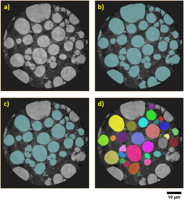
Figure 8. For the laser-milled pillar of the NMC electrode, (a) original virtual slice, (b) segmented virtual slice and neighbouring particles separated, (c) border particles removed, and (d) individually labelled particles.
Download figure:
Standard image High-resolution image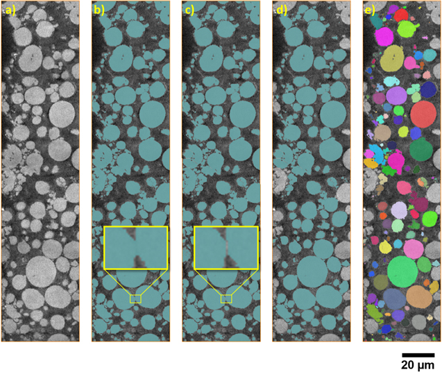
Figure 9. For the merged nano-CT dataset of an NMC electrode, (a) original virtual slice, (b) segmented virtual slice, (c) neighbouring particles separated, (d) border particles removed and (e) individually labelled particles.
Download figure:
Standard image High-resolution image
These particles may not necessarily be representative of the entire electrode because there may be localised variations in mass loading amongst other inhomogeneities. Furthermore, particles that are not fully captured within the tomogram are often removed before quantification of the segmented label field, as illustrated in Figs. 9c and 9d, further reducing the population of particles available for analysis.
By allowing an arbitrarily large number of datasets to be vertically stitched, limited only by equipment time, the analysis of a much larger region of an electrode is possible at the highest possible resolution. The larger number of particles captured significantly improves the statistical relevance of any subsequent image analysis and the overall representativeness of the data as obvious when comparing between Figs. 9e and 8d.
Changes in sample morphology as a result of laser cutting
As shown in the radiographs (Figs. 5a and 5b) and volume rendering of the stitched tomograms (Fig. 5c), there are no differences in attenuation contrast between the edges of the electrode exposed to the laser compared to the bulk of the electrode. As attenuation contrast is a function of mass density, it can be concluded that there are no density variations induced by laser cutting (i.e. no particles have melted as a result of laser cutting). From Fig. 7c, some loss of particles can be observed at the edge of the electrode along with minor pulverisation of smaller particles in the beam path within a few microns of the edge of the electrode. However, these processes are also observed in conventional die cutting of larger electrodes, where material at the clearance between the die and the punch may be pushed or crushed. Thus, the level of precision of technique results in highly reproducible cutting with negligible heat-induced damage to the sample, and it is anticipated that there would also be minimal effects on the electrochemical properties of the sample.
Conclusions
In the quest to maximize capacity and performance in next generation Li-ion cathode chemistries, materials are increasingly being pushed to the limit of their thermodynamic stability. Therefore, to improve the fundamental understanding of the phenomena limiting performance and driving degradation, a wide range of characterisation techniques across multiple length-scales is required to provide information about the chemical, electronic and crystallographic structures of these materials. As the boundaries of spatial and temporal resolution are pushed, significant constraints are imposed on sample size, and it is not uncommon for sample preparation to be complex and time-consuming. Through the use of a laser micro-machining instrument, we have demonstrated the high-throughput preparation of battery electrode samples suitable for nano-CT imaging. It is envisioned that the laser-milling technique presented here will accelerate the in situ and operando characterisation of electrodes at the nano-scale by addressing some of the challenges associated with the preparation of samples suitable for these investigations.
The sample preparation technique presented here has myriad applications in addition to conventional nano-CT: these include characterization methods such as X-ray absorption near edge spectroscopic (XANES) imaging and tomography to measure the chemical structure of other positive Li-ion electrode materials; dark field imaging methods such as ptychography and coherent diffraction imaging (CDI) to measure nano-scale changes in strain within primary particles which may cascade to broader degradation mechanisms; nano-probe measurements where a small sample diameter is desired as each point is individually captured through rastering across the sample; and even to prepare samples for further focused-ion beam (FIB) milling for electron microscopy applications.
In future work, we propose that fully functioning electrodes can be prepared and assembled into suitable electrochemical cells for in situ and operando imaging at synchrotron light sources. With the tuneable probe energy available at synchrotron light sources, X-ray absorption spectroscopic imaging and tomography becomes possible, and the Co, Ni and Mn absorption edges can be investigated through the use of specialized cell designs containing these electrode tabs.
Acknowledgments
This work was carried out with funding from the Faraday Institution (faraday.ac.uk; EP/S003053/1), grant number FIRG001. The authors would like to acknowledge the Royal Academy of Engineering (CiET1718/59) for financial support. Access to the ZEISS Xradia 810 Ultra instrument was supported by the EPSRC (EP/K005030/1).