
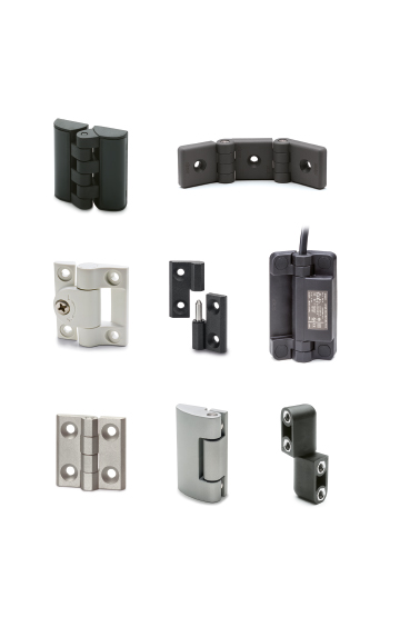


San - Antimicrobial
SELF-SANITISATION AGAINST BACTERIA AND FUNGI
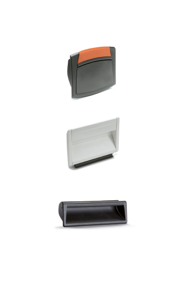
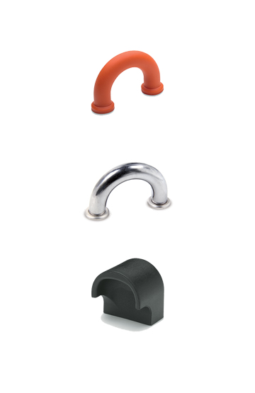
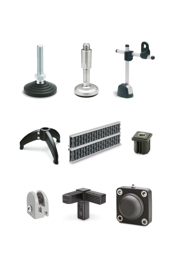
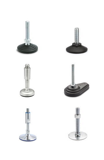
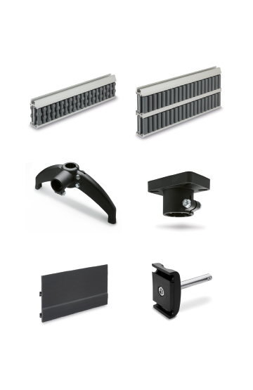
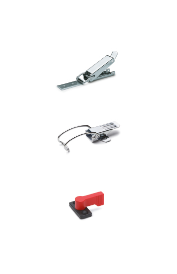
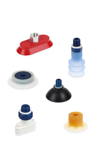
Corrosion resistance, ergonomics, compact shapes and great care in the choice of materials and finishes ease of cleaning
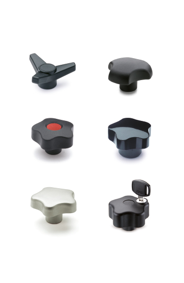
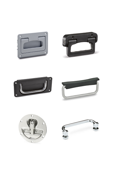
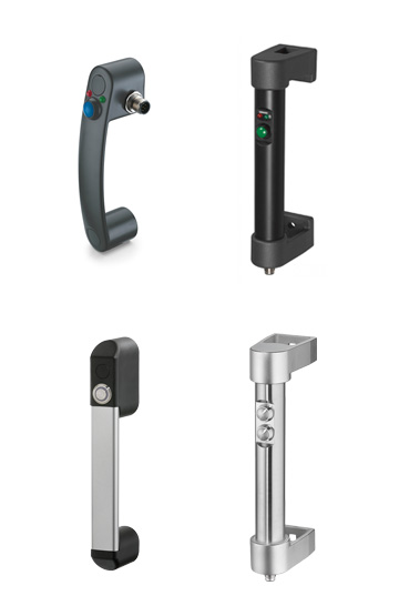
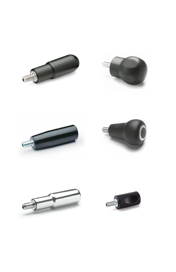
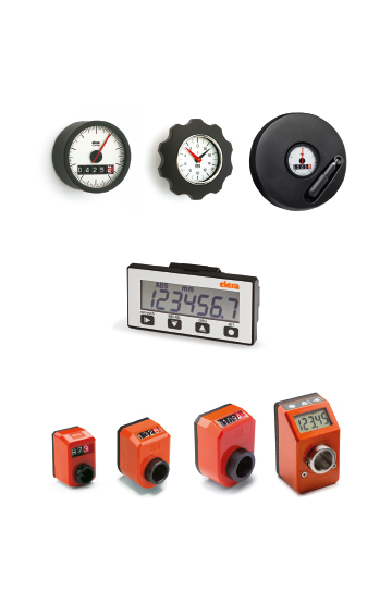
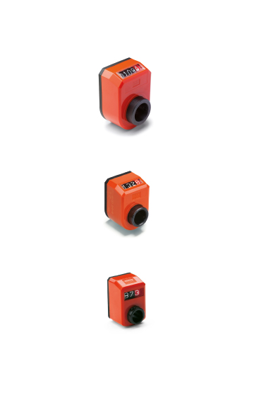
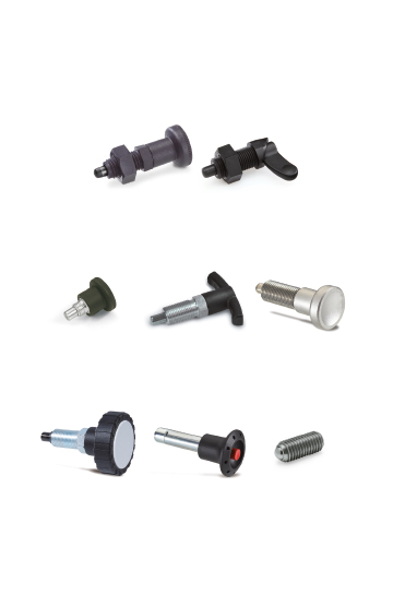
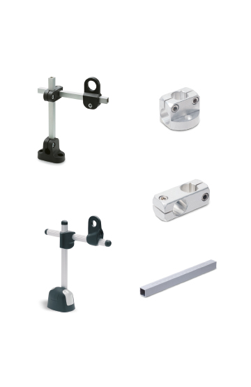
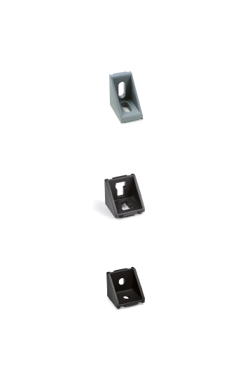
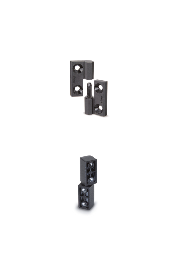
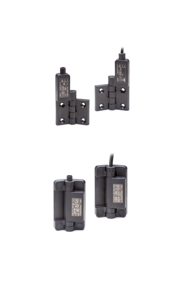
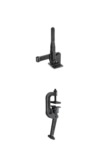
Components for construction vehicles, equipment and machinery which operate in particularly unfavourable conditions
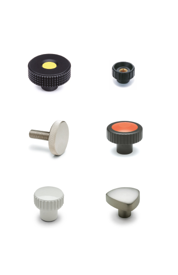
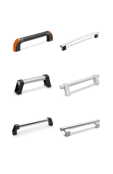
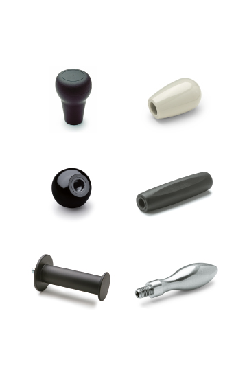
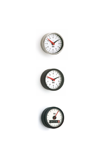
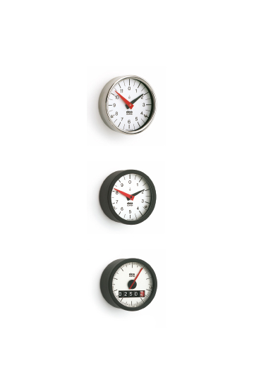
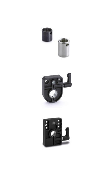
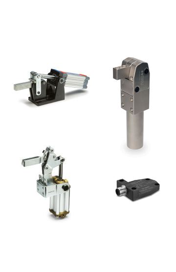
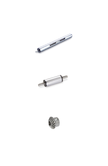
High quality standards, precision in tolerances and care in surface finishes are requirements that ensure greater precision in operation
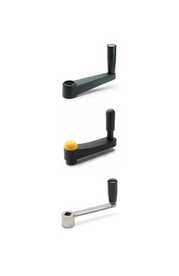
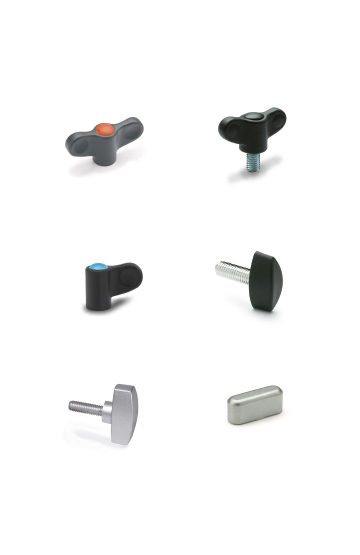
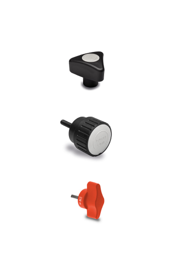
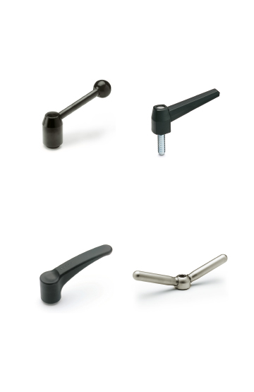
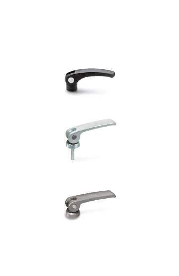
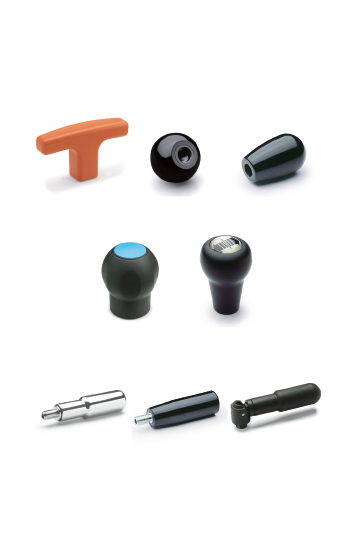
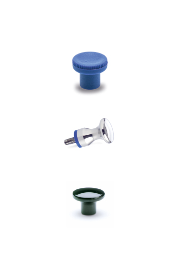
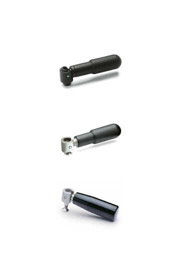
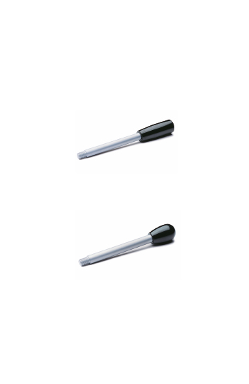
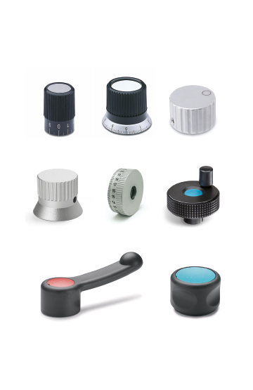
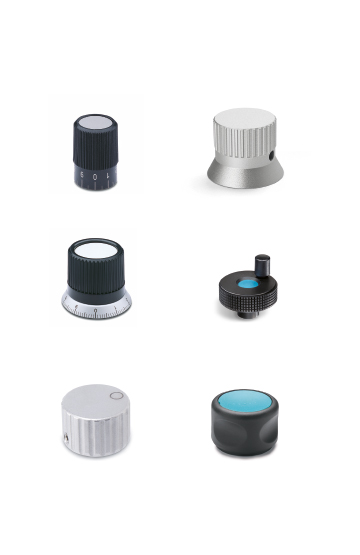
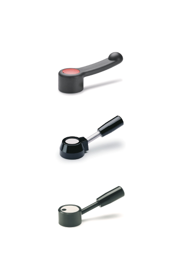
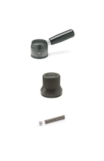
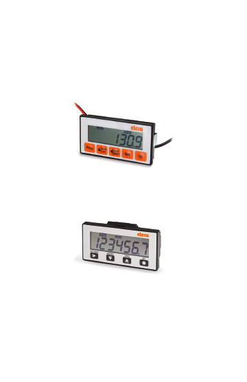
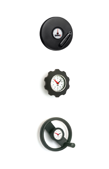
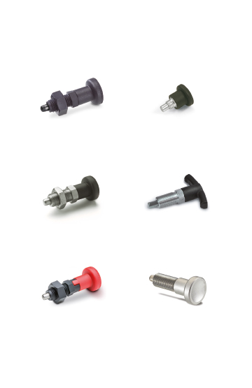
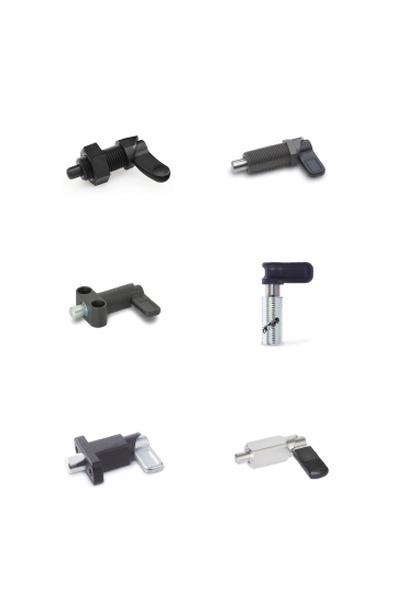
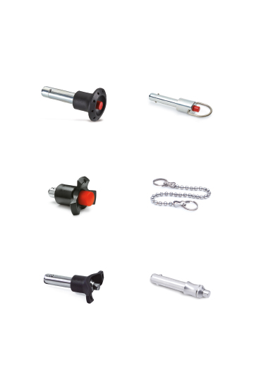
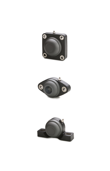
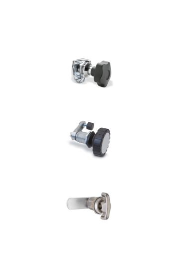
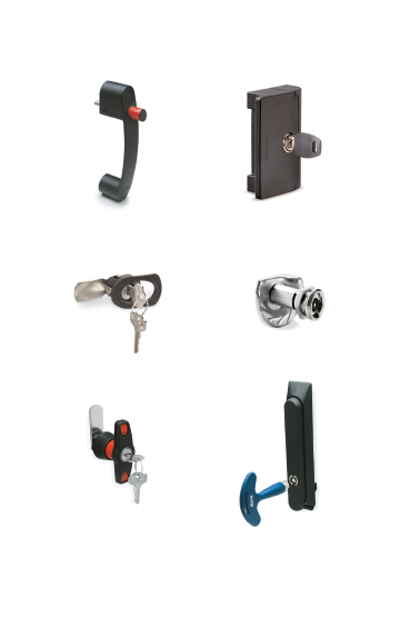
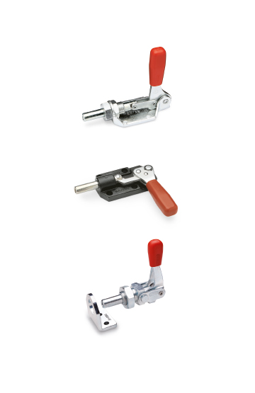
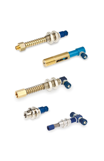
Clamping knobs, adjustable handles and self-locking pins for clamping operations in the field of photography, lighting and electronic equipment
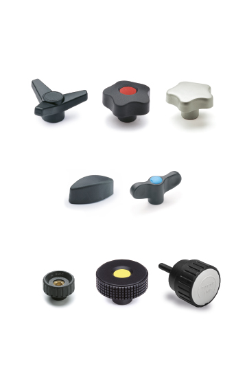
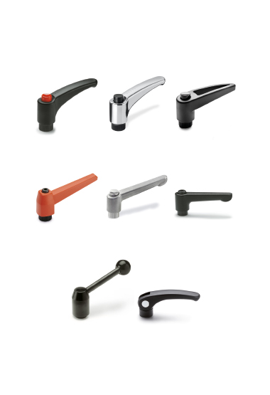
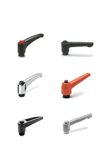
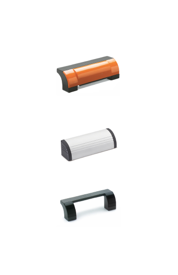
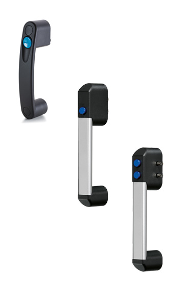
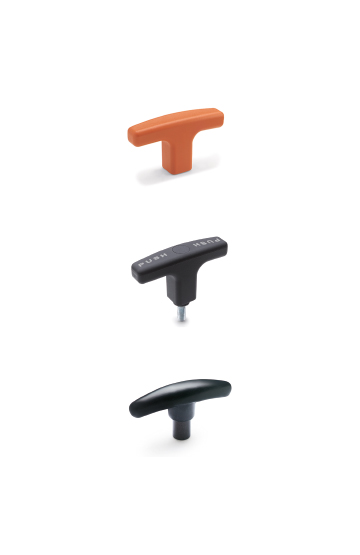
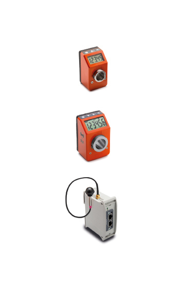
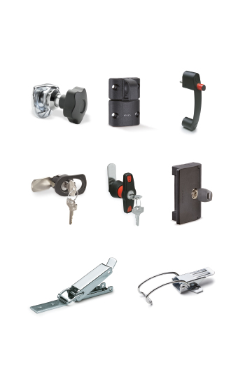
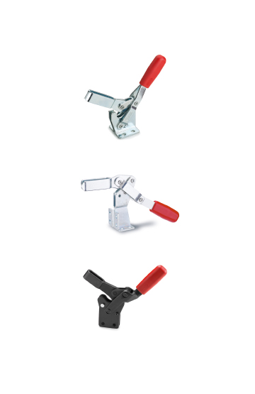
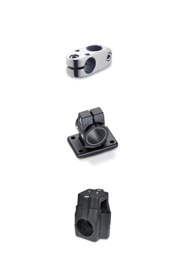
Components to perform clamping and locking operations on machinery or equipment. Ergonomics and design combined with colours
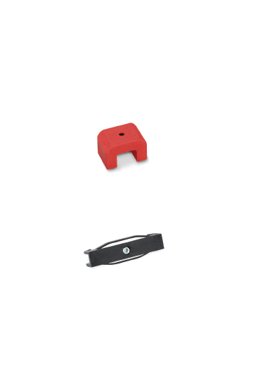
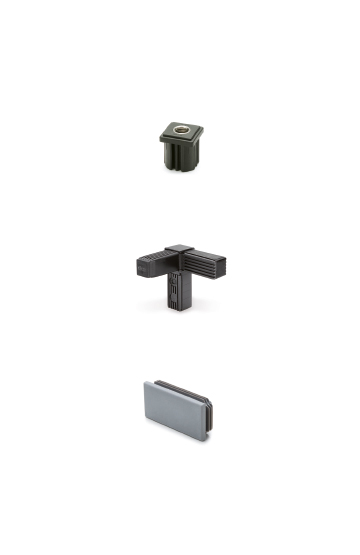
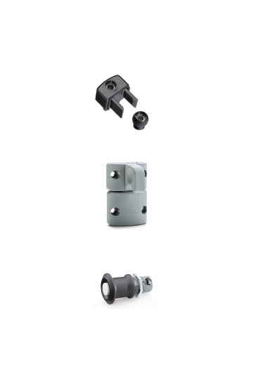
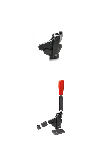
Glass-fibre reinforced polyamide based (PA) technopolymer, RAL 7042 grey colour, matte finish.
Thermoplastic elastomer, hardness 80, Shore A, overmoulded.
Polyamide based (PA) technopolymer, RAL 7042 grey colour, for fastening the clamp to panels of variable thickness (see table).

| s panel thickness [mm] | Adjusting spacer to be used |
|---|---|
| PC.35-4-8 | |
| 3.1 < s < 4.1 | - |
| 4.1 < s < 5.1 | 5 mm |
| 5.1 < s < 6.1 | 6 mm |
| 6.1 < s < 7.1 | 7 mm |
| 7.1 < s < 8.1 | 8 mm |
| s panel thickness [mm] | Adjusting spacer to be used |
|---|---|
| PC.35-6-12 | |
| 6.1 < s < 7.1 | - |
| 7.1 < s < 8.1 | 8 mm |
| 9.1 < s <10.1 | 10 mm |
| 11.1 < s <12.1 | 12 mm |

Black clamps.
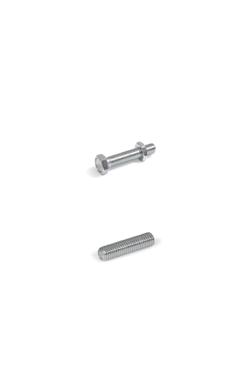
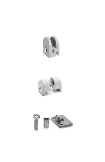
If the clamp is opened, the tightening screw does not yield below an extraction force of 250 N, without coming out from its housing.
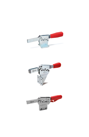
During the tests carried out in our laboratories under controlled temperature and humidity (23°C-50% R.H.), under given conditions of use and for a limited period of time, the maximum load of each clamp is of 100 N (fig. 5).
The tightening screw of the panel and the assembly screws of the clamp on the profile have got the same hexagonal seat. Thus, it is possible to make the assembly by using only one hexagonal key (Key 4).
Maximum tightening torque for the screw = 3.5 Nm.


 >
>

 >
>

 >
>

 >
>

 >
>

 >
>

 >
>

 >
>

 >
>

 >
>

 >
>

 >
>

 >
>

 >
>

 >
>

 >
>

 >
>

 >
>

 >
>

 >
>

 >
>

 >
>
