Building without support? Possibilities and limitations
Michael Wohlfart
Additive Manufacturing Expert | Customer Success Management | Enabling your AM Serial Production
Empathize:
Building without supports or at least minimizing the amount of supports is a hot topic in metal powder bed fusion. The reason is clear: Cost reduction. Not only will the amount of supports have an impact on post processing but also on build time and material consumption.
In my last article, I focused on process parameters to build large horizontal surfaces which were only connected to the build plate at the outer edge (www.linkedin.com/pulse/can-you-build-100-mm-support-free-horizontal-disk-michael-wohlfart). Now, I would now like to emphasize the design aspect. To structure the article, I will make use of the Design Thinking approach.

Design Thinking approach.
Define
In order to avoid supports on your application we should ask ourselves about their purpose. The three reasons for support are:
- Heat transfer
- Residual stress
- Recoater forces
Heat transfer: Due to the reduced heat conductivity of powder compared to solid material, the energy input has to be adapted in overhanging areas. As I have shown in the previous article, the heat transfer topic can be mitigated with an adapted DownSkin exposure strategy and optimized process parameters.
Residual stress: Since metal powder bed fusion is typically what we call a cold process (e.g. compared to EBM or SLS), residual stress is the result of the laws of physics. Stress occurs because of the temperature gradient due to locally concentrated energy input as well as the temperature difference between layers that just solidified and already cooled down ones below them. Material shrinkage is also partially restrained by previously solidified material and can lead to distortion. Rather than working on the cause of residual stress by increasing the build temperature (with the drawback of increased oxygen pickup) or with special scan strategies (with drawbacks on mechanical properties or productivity) it is easier to compensate for the arising effects. Solutions are pre-deformation or, if possible, designs that are less prone to deformation. Below you can see two examples simulated with Amphyon from Additive Works: A flat plate and an upside down cone. Both parts have similar dimensions (50 mm diameter vs. 50 x 50 mm). You can clearly see that the cone shows less deformation because of its geometry. It is starting in one point and then continuously growing in z-direction. Also the circular shape in x-y layers acts self-stabilizing.

Simulation of deformation in z-direction with Amphyon. Stronger curling of plate compared to cone.
Recoater forces: During recoating, forces are acting on the part while spreading the powder. If a part is not connected to the baseplate, it will be wiped away by the recoater. Depending on the geometry and process, these forces will be bigger or smaller. Using a soft-recoater is an option especially for filigree parts but only a hard recoater can guarantee a constant layer thickness. Experience tells: If you can build it with a hard-recoater, you easily can build it with a soft-recoater. This is why the following trial has been done with a hard recoater (HSS blade).
Ideate:
Typical solutions to reduce the effect of recoater forces are for example prop supports, which are frequently used for tall tensile bars to increase the stability of print jobs by reducing vibration of the tensile bars during recoating. If we further develop the concept of prop supports, we can use a shell to protect and stabilize a part. Thereby, no connection to the baseplate would be required.
To start with a simple example, we can start with the cones. A simple Boolean with a clearance of 0.2 mm will provide a gap that is big enough to prevent from fusion of part and shell.

Boolean operation of part and shell in Magics with a clearance of 0.2 mm.
Prototype
The cones have been built on an EOS M 290 in EOS Titanium Ti64 and were easily removable by hand.

Manufacturing of prototype with easy removability of cones.
One could argue that the volume of the shell is bigger than the volume of the part. Therefore, further optimization to find the most beneficial setup is required. At first, you do not have to enfold the whole part but only a certain area in the beginning. The friction between part and shell should be sufficient to hold it in place even for tall parts. Another idea is to stack parts and us the preceding one as a shell for the next part.
Test
Let’s move on to a more advanced design and even incorporate stacking. Since Christmas season is coming up, how about a Christmas tree designed with Siemens NX and tuned with nTopology? By turning it upside-down, the tree is self-supporting and the tree trunk can act as a shell for the next tree. You can see a small overlap of 0.1 mm in x-y-direction between the lattice and the solid parts in order to assure a good connection. For nTop experts: Of course, I did not export the lattice as a mesh, this is just for the pictures ;-)

Two stacked trees in Magics and close-up on the interface.

Amphyon simulation of displacement of lattice part [Source: Additive Works].
After loading the parts into EOSPRINT2, optimized parameters are applied to assure buildability and productivity.

Build plate full of stacked trees.
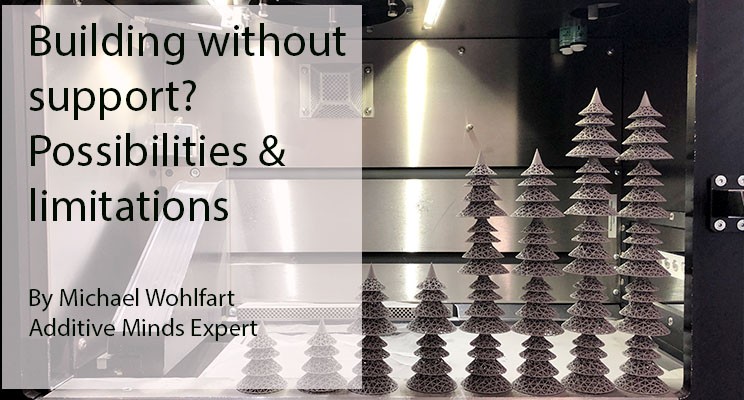
Unpacking of support-free and stacked trees [Source: EOS].


Close-ups on the trees [Source: EOS].
Implementation:
My article covered the first five steps from Empathize to Test. The Implementation is up to you but Additive Minds can support. There are already great examples out there that use just minimal or no support (e.g. the Betatype headlights built on an EOS M 280). I am curious to see what you will achieve.
Laboratory Manager at Aalto University School of Engineering
1yNice, I will carry some tests myself too. It would be helpful for the applications to have some hints about optimized parameters; is it more about reducing downskin exposure or adding DS-layers or must there be delayed layer time to reduce heat buildup.
3D printing
3yThank you! Very informative!
Founder and CEO | AM Printing Technology Innovator | Optics and Laser Expert
3yMichael Wohlfart, Excellent work. One of the few studies addressing accurately the core issue of support material.
Fine Systems Technologies
3yDmitriy Grachev
Applied Solutions Manager - APAC | Additive Manufacturing Professional | Industrial 3D Printing Expert |
4yBrilliant work Michael 👍🏻. You rock.